28.6.15

10" f/8 "Plop" mirror cell design.

*
Running Gui_Plop software for a 250mm x 40mm mirror with 3, 6, 9 and 18 point support produced the following:

The colours in the graphics show deviation from perfect support. [Green]

Blue shows raised areas close to the support points.

While red shows the mirror sagging away from the supports.

The columns of figures alongside show the actual deviation from perfect support in figures

These figures are important because they quantify the changes seen in their respective colour images.

Click on any image for larger graphics and text.

3 point RMS =  2.442^ -06
3 point P-V   =  1.088^ -05

6 point RMS  =  6.323^ -07
6 point P-V    =  3.564^ -06

9 point RMS  =  6.475 ^ -07
9 point P_V   =  3.213 ^ -06

18 point RMS =  2.019^ -07
18 point P-V   =  1.23 ^ -06

Note that 18 point support suggests a ~10x improvement in both RMS and Peak-to-Valley support over a simple 3 point support cell. 6 point support is 3 times better than 3 point but 9 point is very similar to 6 point. The central, red-coloured area is sagging below the desired level but is masked by the secondary. So 6 point support offers the best improvement with least complexity.


Once this information has been absorbed the decision can be made whether [or not] to invest in the far greater complexity of an 18 point support cell. The greater the accuracy of the mirror the greater potential to be gained from properly supporting the primary mirror. The thicker the mirror, the less it will distort.


I Copied the Plop graphic plots into PhotoFiltre to enlarge and move the tables nearer the plotted colour graphics to make them more legible.


Here is an 18 point cell from JMI. Chosen for the clarity of the website image. 6 triangles are balanced on three see-saw bars.[Whiffletrees] So that all support points are pivoted to share the applied loads evenly.   The mirror blank usually rests on slippery plastic "buttons" to avoid stiction. Such complexity is usually reserved for larger and thinner mirrors.


Click on any image for an enlargement.
*

23.6.15

10" f/8 More potty training.

*
A visit to a large DIY store produced some heavy gauge stainless steel washers and two 50mm long coach screws.

The coach screws are of two different sizes. The larger is nearest the primary mirror and will provide more compression load than the smaller one further away.

A collection of stainless steel M6x20mm Allen hex-socket screws have replaced the ugly, hex-head screws between the beams.

It is a shame I did not wait until I had the larger washers before cranking down on the furniture screws. The very thin walls of the beams are slightly dimpled where the smaller heads of the furniture screws applied more local pressure.

Update: The scrap heap came to the rescue once more when I found some lengths of rectangular box section aluminium which slipped perfectly inside the hollow beams. Once centralised in each channel, I drilled through the box sections and refastened the screws with the sides no longer bulging inwards.

 Here is a view between the beams, beneath the primary cell, showing the smarter, stainless steel, hex-socket screws in place.

The neater arrangement of  shorter [50mm/ 2"] coach screws and wing nuts now clamp the cell to the beams via the channel sections without the need for spacers.

Still no attempt has been made to clean up the heavy, beam-bridging channels from their years of lying in the scrap heap. I am quite tempted to make some large-ish holes to reduce their weight a little. Thinner, box-section material would have been better but beggars cant be choosers. Large holes would look smarter and more "techy" than the usual, Swiss cheese look of drilling many smaller holes.

The smaller, cross-ways channel is to accept the axle of the simple trolley wheels salvaged from an old sack truck. The wheels make moving the cumbersome OTA around the garden to find clear sky almost effortless.

The secondary cell, seen from below, showing the thick Tufnol plate to spread the wing nut's clamping loads into the beams.

The  last piece of studding will be replaced with socket head screws and furniture nuts.

The four legged spider, with offset vanes at the central hub, has stiffened up the secondary mirror nicely compared with the rather floppy, curved spider I made first. I have yet to shorten the central stub. Though I may make a new, shorter one and keep the original intact.

The cells have still not yet been painted matt black inside. Nor lined with matt black Funky foam as a possible alternative.

I checked the latest weight of the OTA without finders or primary mirror at 9kg or just under 20lbs. I just checked and a 2 meter length of 315mm spiral wound ventilation duct would weigh only ~6kg. This would increase with the addition of the spider, focuser and mirror cell, of course, but it makes you wonder. Is all this effort with alloy beams and channels really worth the effort? I could have finished a lighter truss tube by now. The heavy duty pot I used for the secondary cell is adding unnecessary weight.


General view of the newly smartened-up OTA relaxing against the hedge. At over 6'6" or 2metres tall the OTA is unusually long for a humble 10" Newtonian. Just the price of using an F:8 mirror to maximise the image quality potential on the Moon and planets. A smaller secondary mirror is possible when using a long focus, primary mirror.

The disadvantage of the offset, alloy cells, relative to beams, is to make the assembly feel very lop-sided when it is carried about. It is fine once fitted to the trolley wheels, but any attempt to lift the OTA by the beams produces a very strong torque effect. Which makes the cells want to drop to their lowest position beneath the beams. This pendulum effect is greatly exaggerated when the primary is in place in its simple cell.

The handle on the top of the cell makes carrying the OTA very much easier, since it supports the offset weight of the primary mirror directly. The secondary cell is much lighter and needs no support when I am carrying the OTA via the handle and middle of the beams.

The twin finders have been removed while I work on the OTA. Telescope "tube" hardly qualifies for this rather unusual, optical support system.

Talking of which: I flatted the domed heads of the collimation  [coach] screws in the lathe. The domes were so high when a self-adhesive [protective] pad was fixed that they were far too close to the height of the true support pads. There was a real risk that the mirror could find itself supported out at the rim. I keep looking at Plop [software] and trying to decide if I should provide 6 or 9 point support. Though at 40mm the mirror is probably thick and stiff enough to be well supported on 3 points at 0.4x the primary's radius.

Click on any image for an enlargement.
*

19.6.15

10" f/8 Beam me up [again] Potty!

 *
I have reconsidered the problem of primary cell torque around the beams as a result of the weight of the full thickness 40mm x 250mm primary mirror. By fixing a second channel section in front of the previous one I now have two clamping bolts to fix the cell more firmly to the beams. Unfortunately the alloy angle sections which locate the cell [pot] to the beams are now splaying. So it's back to how 3/4" / 18mm curved plywood strips might carry the torque loads into the beams to stiffen things up.

I'm still considering how best to implement the idea. Should I clamp an extended tongue between the beams for greater rigidity at the cost of slightly increased weight? It might be better than 1" / 25mm deep formers simply resting on the beams under compression from the two clamping screws.The second clamping screw is now pulling the open end of the pot cell into an egg shape.

One plywood strip with a concave arc improved matters but caused the clamping screws to fight against each other. I think it will take three strips in all. One between the clamping screws and one each just outboard of the screws. The alternative is to use a couple of pieces of studding to restrain the location angle strips from splaying. Or, use much heavier angle to avoid flexure. Or heavy angle and cross studs. Too many choices!

After repeated trials with subtly changed curved plywood spacers I gave up and fitted a single cross brace out of studding to the cell location rails. This was spaced midway between the cell clamping screws and stopped the location rails from splaying. I then tried various spacers on the forward clamping bolt and settled temporarily on a couple of large nuts. These just happened to be the correct thickness to hold the cell pot firmly without too much distortion. With me sitting, quite literally, on the twin spars/beams and trying to push the cell sideways it proved that no more needed to be done. Except to make a smarter spacer and obtain a shorter coach bolt to avoid the unnecessary spacer below the clamping wing nut.

The rearward cell clamping bolt is also far too long by several inches and I will have to obtain a shorter bolt to replace the present one. This coach bolt just happened to be the only one I had in the correct diameter in my extensive collection. The square shank under the domed heads stop these bolts from rotating when the large wing nuts are tightened. This saves me having to use a spanner/wrench anywhere near the vulnerable primary mirror inside the cell.

The images speak for themselves in showing progress so far. The three channel sections between the beams have not been cleaned up since they were sawn from the length which had been lying around for years in the garden. In retrospect I could have sawn a single length instead of three short ones but perfect hindsight is never the same as perfect foresight. At least, not in my case.

The cell pot is still distorted slightly from earlier clamping attempts. I shall remove the pot and press it perfectly round when I remove the clamping bolts to fit the new spacer. I might also curve the strip which lies under the bolt heads to provide stiffness and help to spread the loads better.

Meanwhile, I have obtained some stainless steel, M6x20mm screws to replace the previous M6 studding. The saving on unnecessary complication and slight weight loss is fair reward for the relatively low cost of the new screws. It looks neater too and the heavy channel section resists flexure. A purist would have purchased socket head [Allen] screws but I couldn't find any short ones in M6 at the DIY store. Those they had were bolts so I couldn't shorten them without losing the vital threaded portion.

So it's hex-head and washers to fit into the existing furniture screws for the moment. I shall keep an eye open for stainless steel, socket head screws on my travels. Dismantling the OTA will be much easier with screws instead of studding. It's not so much the desire to dismantle regularly. Rather, the ease of modification without the inevitable mental inertia if I should have further ideas for improvement later on.

PS: I found some socket head Allen screws online in M6x20mm and have placed an order. These will smarten up the appearance even if they are usually invisible. They will better match the socket head furniture screws which are used externally. I'll still need to obtain some stainless steel washers. Despite their large heads, the furniture screws are pulling in the very thin material of the beams when tightened well. I'd rather avoid distortion of the beams if only for appearance sake.

Click on any image for an enlargement.

*

17.6.15

10" f/8 Marine plywood tube revisited.

*
The inherent flexibility of my beam and pot design continues to nag. I am tempted to add plywood braces to the primary cell pot support area to spread the load and kill the torque flexure with changing attitude. However, the present, all-aluminium construction would be compromised by the addition of plywood.

Thin marine ply makes an excellent, lightweight, telescope tube if laminated from two [or more] layers of thinner ply. In Denmark marine ply is known as aeroplane plywood and available in thicknesses of 1/2mm upwards. I rolled a 6" tube for my 5" home made achromat 30 years ago from 2 layers of 1mm.[From memory] It was so lightweight I could hardly believe it possible.

I rolled the thin plywood on a series of plywood circles [stops or baffles] using Cascamite waterproof glue for laminating. I remember the difficulty of bringing the long edges perfectly together to close the gap. A perfect [carefully achieved] dry fit changed with the addition of the glue. So there was a slight hump where the edges could not be pressed down quite perfectly. The tube ended up very slightly pear shaped. Spreading the glue over such large area was a nightmare! A 30cm tube would be much, much worse. Epoxy resin might be a much better bet.

The larger radius 30cm diameter tube might better suit 1.5mm laminations but I have no idea as to its flexibility in this thickness. I would need to find a model shop stockists and apply some bending pressure to various samples.

I believe from searching online that this special ply is only available in 1.5m x 1.5m sheets. [Roughly 5'x5'] A standard ply sheet size of 1220 x 2440cm [4'x8'] would be more economical and avoid a seam. I had exactly the same problem with the cardboard tube. Which ended up much heavier after two layers of concrete form tube were glued together to achieve the final length. I shall have to do some calculations to see if the weight and cost of the plywood makes the project completely pointless.

1m^3 of marine ply  = ~700kg  Aluminium has a density of 2700kg/m^3
Or nearly 4x the weight of the densest Birch plywood!

Area of tube material = Circumference x Length.

Volume of materials = Area x finished thickness = [3mm or 0.003m]

30cm tube = 0.03m diameter x Pi [3.142] = 0. 94.26m

x 2m = 1.8852m^2  x 0.003m =0.0056m^3

0.0056m^3 x 700[kg/m^3] = 3.92kg.

So a bare tube, 2m long, made of 2 x 1.5mm layers of laminated plywood weighs about ~4kg or about 9lbs. The weight of the adhesive/resin required shouldn't amount to much.

The bare 30cm tube would probably need some local reinforcing. Cross-grained circumferential strips laminated around both ends of the tube would help. The plywood tube would be no smaller than the present cardboard one but would be about 1/3 the bare weight! It's just a shame the sheets are only 1.5m square. When I really need 2 metres long for minimum wastage and to avoid the extra work required in laminating it up from smaller sheets with close [hopefully invisible] joints.

My attempts to get local builder's merchants to source me some 1.5mm aeroplane/marine plywood has been an exercise in frustration. I am being quoted £100[equivalent] per sheet for delivery alone for just sending it half way across Denmark. I can halve my material costs by buying from Holland. The stuff is made from birch veneers in Finland so it probably passes through Denmark on a lorry to reach Holland. £100 a sheet for delivery does not compute! A plywood scale model of the Concorde would cost more than the original aircraft! The Dutch supplier suggests on their website that they can roll their thinner plywood sheets and pop them into a cardboard box for compactness during delivery. A simple skill obviously not found in the Danish suppliers!

*

7.6.15

Extending the 90mm Vixen Dewshield to combat dewing.

*
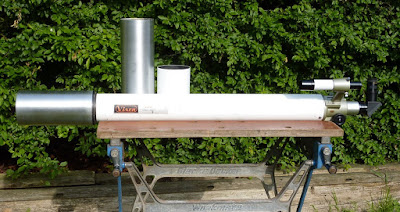
My little Vixen 90M 90mm F/11 achromatic refractor had proven to be rather prone to dewing of the objective under certain observing conditions. Then I realized that I had been hoarding a length of 100mm diameter, thin aluminium tube amongst my collection of potentially useful materials. This tubing fitted only slightly loosely on the front stub of the Vixen objective cell. A turn of electrical tape was all that was required to provide a nice sliding fit. The original Vixen dewshield had soft ribbon as 'packing' glued on the inside at one end to avoid scratching the cell's paint finish.

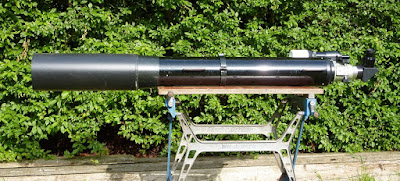
It took a while working in the lathe, with a wooden plug for the tailstock end, to remove years of weathering from the exterior surface. After using coarse abrasive paper to cut down to bare metal I finished off with steel wool and then a scrap of Scotch-Brite fine abrasive fiber to get a fair finish. The finish is certainly not perfect but it will serve its purpose in the pitch dark, in the privacy of my secluded, rural garden.

For the new dewshield, I used an old fashioned or "classic" 2.5 x D multiplier instead of the Vixen original's 1.5 to provide extra length. Most modern refractors, and APOs in particular, use the shorter 1.5 x aperture dewshield length to give a stumpy look and to emphasize their already short focal length. And, no doubt, to provide greater portability and reduced storage requirements. Some dewshields are retractable or even reversible to further reduce the length of the instrument's storage case or bag.

On the Vixen I had always felt slightly cheated because the original dewshield looked rather too mean to my eyes on an F/11 OTA. Not quite a "classic" F15 refractor but definitely looming towards it.

Note how much of the original dewshield length is already "lost" on the 52mm long, extended front of the protruding objective cell beyond the dewshield's supporting ring. A real cynic might argue that the strangely distorted form of the objective cell is a cynical marketing ploy, by Vixen, to pretend that the M90 is a shorter focus instrument or even a semi-APO. The cost of such a deep casting, merely to hide the true [effective] length of the instrument must considerably outweigh the cost of 2" greater length of main tube material!

Choosing the visual balance between "nose heavy" dewshield lengths and long thin main tubes must be a difficult one [a nightmare?] for refractor manufacturers these days. They must cater for all of those who are buying an instrument entirely on appearance alone. Most of whom aspire to an "exotic" APO rather than the classical, long focus refractor. A long, skinny main tube now looks slightly old fashioned despite the optical and practical benefits of owning a long focus instrument. An achromat wants to be as long as reasonably possible to minimise false colour and allow for comfortably long eye-relief eyepieces.

The unused effective length of the Vixen dewshield certainly did not help it to resist dewing! In fact I could have made the new dewshield even longer to allow for the 2" of wasted length lying over the extended cell. I wish I'd thought of it at the time. Though I do have a slightly rougher length of tubing left to play with if I get really desperate. See later added images for a 2.5 x aperture dewshield allowing an extra 5cm for the objective cell, forward extension. I think the [unadjusted] 2.5D dewshield probably looks best on this particular F:11 90mm Vixen refractor. A longer F:15 would probably benefit from a compensated 2.5D dewshield to remain in scale.

For my equally dew-prone, 150mm F:8 refractor I have a nice long, "memory-plastic" tube to slide over the original and ridiculously short dewshield. This thin, but stiff, black plastic came in an inexpensive, pre-curved roll intended for some gardening purpose which I have now long forgotten. Its natural tendency to curve tightly to rather a small cylinder avoids sloppiness or the need for ugly clips or clamps in use. If this plastic was sold by telescopes dealers, as dewshield extensions, it would probably cost £100 instead of mere pocket change. Note the ludicrous scale of a 2.5D, 47cm long, dewshield on such a short focus F:8 6" refractor. It is no wonder they cheated on dewshield length!

I really need to clean the Vixen objective lens while I have the cell unscrewed from the main tube. [Separating the cell from the main tube for the first time is a whole story in itself!] BTW: What looks like a rather shiny flange is actually the female thread where the cell screws onto the main tube.

After removing the securing rings I lifted the glass doublet by gently lowering the cell over a short length well-padded tube or stand. Those who haven't learned this trick will probably just tip the cell upside down only to find the glass stuck fast. Or will drop the objective glass right onto the floor!

The close fit allows the glass to tilt against the inner cell wall causing it to jam. While standing a stable length of tube upright on the bench, with a few layers of tissue on top, ensures the amateur can safely lift the glass objective free of the cell without tilting. Even a drinking glass will do as a lens removal stand provided it is padded to avoid scratching the delicate lens coatings.

I used a rubber bulb, lens blower to remove any accumulated dust before gently using lens cleaner on the objective with lens tissue. As is typical for any lens over about 75mm the glass elements are not cemented. So great care will be required to avoid them sliding apart once they are no longer co-located by the objective cell.

The Vixen, like my other refractors, is always stored upright, on its "nose." [Dewshields resting on the floor.] However, the focuser is not remotely air or dust tight even with an eyepiece, star diagonal or sealing plug in place. So the back, as well as the front of the objective, slowly gathers dirt over the years. Anybody with a functioning memory would probably remember to drop a loose plastic bag over the focusers after use, but there we are.

It has been said that a cloth bag over an empty focuser is better. Since this allow the OTA to breathe with changing humidity and temperature. A plastic bag or sealed container of any kind will trap moisture inside the OTA. Putting away a soaking wet instrument is asking for trouble. The moisture is trapped and may eventually attack the lens coatings. Long term storage ought to be indoors where humidity is much lower than an unheated shed or garage. Capping an objective while still wet with dew is also unwise. The irony is that bringing a cold instrument indoors will provide a thick layer of dew. This must be allowed to evaporate by itself on the lens. Wiping it dry is prone to damage the lens surface.

I have lined the longer Vixen dewshield tube with thin, matt black, "Funky Foam" to kill reflections and reduce thermal cooling effects. Most objects radiate their warmth to the night sky. This can even super-cool an instrument below ambient temperature. 

It is interesting how the semi-polished alloy dewshield tube looks smaller in diameter than the white painted original. At least it does in the top picture. Yet they are identical in size apart from their length. I'll probably not bother with priming and spraying the new dewshield white to match the main tube.

Click on any image for an enlargement.

*