25.7.15

10" f/8 Too many tubes!


*
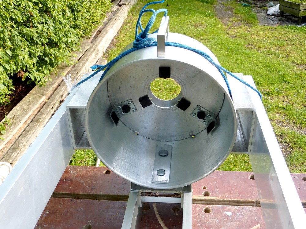
The image shows the three options tried so far in the search for a lightweight 10" F:8 OTA. All the OTAs are 2metres or 6'6" long and propped up at close to the same angle. Carrying the 6mm/ 1/4" thick 30cm/12" diameter cardboard tube around is very hard work due to its awkward length, considerable weight and diameter. It cannot be easily bear-hugged for carrying due to its sheer size. It is far too tall to go through the shed door without bringing it down to the near-horizontal. Adding U-shaped "drawer" handles would help but even the bare weight is simply too much for me to want to carry it far. That extra weight is a serious hurdle to enjoying the telescope as often as possible.

The "spar" or "rail"" OTA, with its two supporting under-beams is very awkward to carry without the primary cell handle. This handle is essential  to resist the cells swinging strongly to their lowest position. The all aluminium OTA is also rapidly gaining weight with each new attempt at torsional reinforcement. Moreover, there is nowhere sensible to attach Dobsonian altitude bearings on so narrow a spine. They would intrude into the light beam. Even if I could fit altitude bearings the design would need heavy counterweights to balance the offset masses of the heavy cells.

The twin lateral beams + plywood rings and 3mm / 1/8" thick, cardboard stub tube design is light but unlikely to be stiff enough without many more [and thicker] support rings. It may also prove to need stiffening spars at the top and bottom of the "tube" to help resist lozenging. Altitude bearings are easily attached to the side beams and there are no offset masses or moments. The balance point will dictate whether a [third cage] centre section is required.

I really need to rout some more rings in thicker and stronger material to establish this OTA's true practicality. The present plywood rings are only 10mm thick and feel rather flimsy. My stock of scrap, 18mm [actually measuring 17mm!] multiply Birch plywood feels very heavy in comparison. So 15mm rings may still be too heavy and 12mm BWP Birch ply may be the best option for weight and stiffness. Though that still leaves me wondering about fixing the rings to the cardboard tube and beams. I can't drill through the 12mm thickness of the plywood rings. So may have to add thicker plywood 'tabs' to take short screws and nuts. With luck the tabs can be designed to help to resist the rings twisting on the beams. They could even bridge between pairs of rings to take a greater number of screws.

I still have the 16mm [0.6"] wooden dowels I first intended to use in making an OTA. Though these would require that I rout many more tube rings. Then precision drill them for the multiple, dowel stringers equally arranged on a circle. Such skeleton or cage, tube designs were more popular before triangulated trusses became the norm. An all wooden dowel and plywood ring design would need serious protection from the weather and unheated storage. Attaching Dob altitude bearings to the cage might be difficult unless the tube rings were locally modified.

There is still no free lunch when it comes to weight: Eight x 2 meter lengths of 16mm dowel weigh exactly 4lbs. The 30cm bore rings [in 10mm plywood] weigh half a pound each. Unfortunately the dowel-cage design needs more rings to retain stiffness compared with aluminium tube. So eight rings are likely to be about the minimum. 8lbs doesn't sound like much, but the mirror, cell, spider, focuser, finder[s] and secondary have to be added to that figure. The most immediate problem with a cage is accessing the mirror to cover it. Leaving out one dowel to make an opening near the mirror would weaken the cage at the worst possible point. The rings could double as light baffles but might still require a black, cloth shroud.

The image of the latest OTA idea shows a quick mock-up using a second ring on the lower cell. The notches in the rings have been deepened to take the full depth of the 17mm, hollow beams.

The 12" cardboard tubes have an important function in keeping the beams from moving parallel to each other. Or rather, would if there were four supporting rings instead of only three. With just the bare rings there is very little longitudinal stability as the rings easily twist and collapse.

As a belt and braces approach I hoped to source some 2m lengths of 1" square alloy tube. These would to go at the top and bottom of the rings but the only nearby stockist had none in that length. They may well be unnecessary as the beams have such depth that they are very unlikely to bend in the vertical direction. I am still mulling the best [lightest and strongest ] way to fix the beams to the "cells" in a cosmetically attractive way. I don't want to drill bolt holes in the new beams until I am quite sure they will be where I want them and in the correct size.

Click on any image for an enlargement.

*

21.7.15

10" f/8 Side beam mock-ups:

*
Seeing the appearance of the side beams in practice helped me to decide if I really wanted to continue. The earlier supporting beams were certainly sleeker but seriously lacked torsional rigidity. The primary cell would sag around the beams with changing attitude of the OTA on the equatorial mounting. This was disastrous because it meant constantly having to re-collimate the optics every time I moved to another object to observe. Adding side beams would have helped but looked just too damned ugly! The lower paired beams should have been reduced to only one lying flat. With another mounted on top to make a four beam arrangement.

First mock-up with side beams hanging from cord on the original OTA to hold everything together. Focuser still pointing straight up. The original supporting structure is intended to become obsolete when the side beams are firmly attached.

Another early mock-up with wooden strip spacers and cord to roughly judge the side beam positioning and spacing.

The secondary cage has been turned by 45 degrees here to bring the focuser to a comfortable angle for altazimuth use. The finder mounting bracket is now on top of the OTA for right eye viewing. Though it is easily moved to a new site simply by drilling a single hole for the mounting screw. The upright focuser was fine on the OTA when equatorially mounted. But would be difficult to reach with the OTA altazimuth mounted on Dobsonian bearings.

If a smaller section, rectangular alloy tube were readily available I could add them to the tops and bottoms of the OTA for altazimuth use. Builder's spirit levels use such sections but I have not yet seen these available as "bare" rectangular tubing. Certainly not in readily affordable 2m lengths in DIY outlets. The bending loads on an altazimuth OTA are very different from one which is equatorially mounted. With an altazimuth the bending forces are mostly in the vertical plane except when the tube is being lightly pushed in azimuth.

The rectangular, alloy, side beams provide excellent vertical support due to their considerable depth. When the beams are placed "flat" that depth is absent and the beam is not remotely as stiff in that orientation. Thus it would make little sense to add these much larger beams at the top and bottom of the OTA for altazimuth use. The greater dimension of the beams would become complete overkill in the horizontal plane and add little more than unnecessary mass.

Though the main beam's wide spacing does already add considerable lateral stiffness. Which will depend on firmness of attachment to the cells. Adding two more [large] beams top and bottom would make excellent sense for an equatorially mounted OTA. Which subjects all of the beams to every possible orientation in use.

In the end I have decided to use more [heavy] channel section to make some really strong beam-spacers for the primary cell. Narrowing the 2" high channel webs by 1/2" made the side beams parallel despite the alloy secondary cage being slightly larger than the primary cell. As was the plywood rings and 30cm cardboard tube secondary cage. I am still not completely sure that simple compression, with through, clamping screws, will hold the pot firmly to the channel and beams. I was considering adding rubber hose, slit along its length, to the long edges of the webs for more friction and to reduce cosmetic damage to the primary "pot."

These images show further mock ups with the side beams and channel spacers still hanging from cord. When finished, this beam arrangement should provide serious stability and lack of flexure in the primary cell without needing the former [and much heavier] support beam system down below.

The Dobsonian altitude bearings can be attached to the side beams via a sliding clamp system to allow for easy, coarse balancing of the OTA.

These 5" long x 4" alloy channels @ 1lb each weigh no more than the 4" x 1" timber which I first considered for beam spacers. I might well invest in a decent quality, 3/4" metal hole saw to reduce the mass of these channel sections even more.

With the compression loads applied over such a large area the beams should remain firmly attached to the alloy pots without twisting. Internal reinforcing strips will support the clamping screws where they press on the primary cell just as they did before with the spar or "under-beam" system.

Removing the lower spars produced a minimalist but rather odd looking OTA. Because it looked too wide the great length seemed to have shrunk.

The introduction of  multiple baffles between the beams would help to improve OTA stiffness locally at the cost of increased weight. Unless these baffles were joined together by stringers there would probably only be local resistance to lateral, beam bending.

I am keeping an open mind about using the plywood rings and cardboard tube secondary cage in preference to the existing alloy pot. They are both the same width between the beams in practice. So require no beam modification for a straight swap later on to save a little weight.


Click on any image for an enlargement.

*

8.7.15

10" f/8 Altazimuth Dobsonian OTA ideas.

*
I am currently re-pondering my options. Perhaps using a Porsa primary cell framework with 30mm diameter truss tubes. The problem then is knowing how "tall" to make the primary cell to allow the direct attachment of altitude bearings without having the truss poles and cell framework to hand.

Substituting two more, 2 meter long, builder's straight edges would leap that hurdle at one bound. Leaving the whole truss problem and altitude bearings irrelevant. But, requiring yet more serious thought as to lightening the secondary cage without loss of stiffness. Perhaps I should utilise a single ring with a right angled surface for finder and focuser support? Or mount the focuser to look through one of the alloy beams? 

Well, I finally made a decision and bought two more beams. They sell for just under £20 equivalent. Which is good value compared with the price of 2m of Porsa square tubing or buying 2m lengths of round tube online. These builder's straight edges are also readily available in most large DIY outlets.

I weighed the pair to remind myself that they are dead on 3 lbs each. [~1.4kg] So 4 beams will be 12 lbs bare of cells, mirror, focuser and finders. Since I will attach the beams to the sides of the cells I shall have complete freedom to mount arcs or full circles for Dobsonian altitude bearings.

Hanging the beams temporarily in place, using cord on the horizontal OTA, suggested I choose a new focuser angle to match an altazimuth mounting. Should I rotate the existing cage to make the focuser horizontal or [perhaps] 45 degrees above the OTA axis for greater viewing comfort? It really ought to be on the left [looking up the tube from the primary end, to make finder use more sensible.

I bought some suitable M6 stainless steel coach screws, some nuts and matching washers while I was in the builder's merchant. I still have several lengths of 30cm [12"] diameter, cardboard tubing left to mock up a new secondary cage. So might explore that route instead of drilling new holes in the existing alloy cage. It won't matter if I make a complete mess of attaching the beams to the cardboard tubing while I try out some different ideas. Even placing the fixing screws will mean the hidden, central web must be taken into consideration when drilling the beams. It would help to resist crushing the beams. 

I'd also like the altitude bearings to be able to slide and clamp anywhere long the beams for achieving OTA balance. Just like I did with the equatorial mounting. This saves having to use adjustable sliding counterweights on rods. Or attaching separate counterweights to the OTA. I know from long experience that anything heavy which has to be carried around, or attached later, is just another impediment to regular telescope use.

iStar optical are/were offering skeleton tube refractors. Though they use 3 beams and multiple CNC'd metal support rings which also act as the light baffles.

Using four builder's straight edges would provide a nice, stiff and lightweight OTA for a long focus [classical] refractor. The beams come in lengths up to 3m straight off the shelf. Which would perfectly suit an 8" F:15 refractor made with a four beam skeleton tube some 10' long! How well the Fullerscopes MkIV mounting would cope I have no idea. Though there's always the Beaconhill MkII mounting for such huge telescopes. I would probably need a much taller pier to avoid grovelling on my knees when pointing at the zenith. Well, one can but dream! ;ø))

Today I weighed the secondary cage [metal pot] and found it to be 6lbs without an eyepiece or finder. So then I immediately cut an 8" length of the 12"/30cm cardboard tubing to replace the pot. I tried to make some tightly fitting 1/4"/6mm thick plywood, external stiffening rings. This proved that cutting out the bores of the rings with an electric jigsaw was not nearly accurate enough!

So then I spent some time making a new circle cutting jig for my Bosch router. This will have a capacity of about 24" diameter circles and be infinitely adjustable. A centre pin is provided by Bosch for making circles using the adjustable fence but I found it all but useless. To make smooth, accurate circles requires a really sturdy centre pin in a pre-drilled centre hole. Certainly not just a point resting in a shallow dimple in the wood to be cut. Making the circle cutting jig larger than my immediate needs will allow me to cut large radius, altitude bearing arcs later on. Once finished, the router jig made some smoothly round circles which fitted the cardboard tube exactly.

The image shows one routed ring in the foreground against one sawn ring in the background. The cut-outs in the scrap plywood rings are for the alloy beams. I am still experimenting on a replacement secondary cage so don't want to waste Baltic birch ply at this early stage.

Try to ignore the deliberate mistake in routing my old workbench top. Last time it was with a circular saw so I'm not really improving with time.

Routing a ring is not quite as easy as it looks. You can easily have a perfect bore or a perfect circumference. Getting both requires some means of retaining an immovable centre hole for the circle cutting jig. Nor can you use clamps as the router base will hit them. Ideally it needs a large, router cutting board. Made with a sacrificial top surface which will still accept screws to hold the centre circle cut-out perfectly still aftwer the router cut is completed. For the occasional cutting, of just a couple of rings, this seems too much like hard work.

A temporary lash up with the beams fitted in the ring notches suggests there is real potential to this new design. The shoulders of the notches are critical in resisting twisting of the rings around the beams. Adding a similar central section, like the secondary cage, would help to stiffen up the OTA without affecting its moment. The use of cardboard tube and plywood has the advantage of thermal neutrality in changing temperatures. Though the alloy beams do remain.

The iStar TCR [refractor] is certainly attractive and remarkably lightweight but doesn't readily lend itself to an altazimuth fork mounting.  A Dobsonian needs lateral supporting beams for fixing the altitude bearings on either side. The [light coloured] mounting clamps can be seen attached to one of the longitudinal beams or stringers. Notice how all the reinforcing rings are bored to match the light cone and thinned to save weight. In light polluted observing conditions a tubular sleeve of black cloth could be added. Much like the shrouds applied to truss Dobsonian OTAs.

Each beam would need to be bolted to the rings and/or tubing. I envision a rectangle packing piece between the beam and the cardboard tubing to avoid local crushing. Perhaps with two parallel lengths of dowel attached to spread the crushing loads into the cardboard tube. The rather weak plywood, which I have used so far, would be much improved by substituting Baltic Birch, multi-lamination plywood. Perhaps in 10mm, or even 12mm thickness to keep weight down at the secondary cage end. The rings would need to be glued firmly to the cardboard tube to ensure there is no rotation between these components or all stiffness would be lost. I am unsure how much "meat" should be left at the bottoms of the notches to resist the ring crushing the cardboard tube or vice versa. These suggestions are to further strengthen the beam's ability to avoid twisting against the tube/rings and to avoid crushing forces when the beams are bolted to the rings. It is not as if the forces are trying to ovalise the tube. Rather, that the crushing force is applied to the rings via the bases of the notches.


Click on any image for an enlargement.

*

3.7.15

10" f/8 A tube by any other name?

*
Once I decided I might build a Dobsonian out of my 10" F:8 I realised that I had now made an even more difficult job for myself. The narrow, offset beams, relative to the cells, did not offer any easy way to add altitude bearings. The offset between the centres of mass and the beams would cause all sorts of balance problems.  So what to do?

The automatic choice would arguably be to make a smart, truss tube Dob. Okay, I thought, start looking for some suitable truss poles. How difficult can it be? Hours [and more hours] of browsing later I'm looking at well over a hundred pounds equivalent before freight charges. I chose 25mm diameter in aluminium, with a nominal 1.5-2mm wall thickness. Many metal stock holders won't entertain private sales. Their suggestion of approaching a local smith or engineering company to order on my behalf is unlikely to make the tubing any more affordable. £50+ for a 3 meter length would need hundreds of quids worth before I started cutting it up into useful lengths with huge potential wastage.

An alternative is to use the Porsa system and buy square truss tubes from their storage frame, building materials. Well over £120 equivalent plus £25 in freight but at least I get a choice of colour. Elox silver, black or white and the lengths I want. Not certain I like square truss poles but it makes for much easier construction without the need for clamping. A simple bolt would do as it wouldn't need to be dismantled for transport.

Then I remembered that round curtain poles come in 25mm diameter x 1.5mm, thin wall, aluminium tube. Or rather did, according to my completely fruitless, online searches for Café style poles. The prospect of touring every charity shop on Fyn in the vain hope of sourcing suitably matching material will make it a very much travelled pile of tubing. I drew a complete blank at the 3 nearest and the next candidates are over ten and over fifteen miles away! This too proved a complete waste of time. Though I did discover some 2m long x 25mm diameter tubing in a builder's merchant. Sadly they sell at 140DKK each or about £14 per 2m length with a pretty 'elox' silver finish to the 1.5mm wall aluminium. Eight of those tubes for a truss is about the same cost as the Porsa system in 25mm square tubing. I would want to be much more sure of the validity of my design before launching myself in that direction.

Cardboard tubing might still beckon if I were willing to ignore the massive weight [and cost at Danish wholesale-resale prices!] Knowing how heavy and cumbersome my DIY laminated cardboard tube turned out was fair warning not to follow that route again!

Aeroplane plywood is still only a distant hope with exclusion barriers to private sales by the only Danish stockists. Or, put up with rip-off retail charges per sheet and obscene delivery charges. Though I could always go direct to the Dutch stockists and save a fortune. They say they would just roll the sheets and pop them into a long box. A skill well beyond the grasping Danish re-salers who want £100 per sheet for delivery regardless of quantity ordered. Thereby pricing themselves safely out of any chance I would ever trouble them with an order. Another, more sympathetic, builder's merchant manager hopes to be able to supply at more modest prices if I am prepared to be patient. We shall have to see what turns up from that source.

An alternative is to buy some more builder's straight edge beams and arrange them firmly at the sides of the cells [pots] to support the altitude bearings directly. Two more beams, at top and bottom, would make a fairly affordable and hopefully rigid tube. Though its beauty would definitely lie in the eye of the beholder. I also have some slight doubts about the sharing of the tension-compression loads of the beams via the relatively thin pots/cells. Perhaps I should relax my objection to plywood and build the cells as boxes of 1/2" 12mm waterproof birch plywood?

Here's a superb [prize winning!] 10" F8.8 Dobsonian by Mike Lockwood: It's even longer than mine but balances very low to the primary cell thanks to its much lighter secondary cage! My heavier pot/cage would need a very much taller rocker box. Possibly leading to very different handling qualities when pointing the telescope.
 
http://www.loptics.com/ATM/telescopes/10in_F8p8/10in_F8p8.html

Discussion with the owner/builder suggests I could usefully increase the size of my truss tubes and beef up the rocker box for windy conditions.


 *