28.8.15

7" f/12 iStar refractor 6: Focuser backplate.

*
My attempts to line the new tube rings with strips of foam proved slightly more demanding than expected. Cutting the foam went rather badly despite the foam being rested on a smooth cutting board. Even a brand new hobby knife blade snagged repeatedly in the "sticky" plastic foam.

Cutting the foam with scissors produced rather ugly scallops. The foam strips had to be clamped level in the workbench vice jaws and "sanded" smooth. Using finer grades eventually produced an acceptable surface. Then the contact adhesive I intended to use had dried up in the bottle. The remaining liquid lying on top had zero gripping power even after waiting overnight for it to dry.

Then I tried thin, double-sided tape. This worked well but I'm unsure of its long term holding power when repeatedly dampened with dew. The grip of the foam on the tube is so high that it probably wont slide easily through the rings when needed for re-balancing. Not a serious problem since the clamps will just need to be opened with the declination axis locked in the horizontal position. The tube can then be lifted free and moved along as desired.

Another tour of the village recycling shops produced some cheap saucepans and baking utensils. I needed two items of exactly 8" OD in aluminium. One to house the lens cell [sometimes referred to as a counter-cell] and the other to act as a fairly solid tailpiece face-plate for the focuser.

Without having seen the objective lens cell I am a little unsure exactly what I need. The solid saucepan will be very stiff once inserted into the main tube rim first. The heavy aluminium base will provide a good, solid surface on which to mount the focuser. A little extra weight here won't do any harm as it will help to balance the OTA.  The walls of the deep pan in the foreground have only a small amount of taper.[~1mm overall] This should allow the pan base to be brought flush with the main tube if pressed in rim first. The pan walls would be cut down to only a couple of inches high to provide a shallow end cap to the main tube. This cap could then be fixed securely with small screws through the walls of the main tube and the pan.

The lighter shell [fitted into the main tube in the picture] would be cut away to leave a large hole the size of the rear of the objective lens cell. Its depth may help to sink the vulnerable lens into the protective end of the main tube. Two identical saucepans could have served at each end of the main tube. However, the other one I brought home was a little larger by a millimeter or so. I am unsure whether it will safely press into the end of the main tube without causing damage.


The last thing I want is to force the folded seam of the main tube open and weaken the tube. This other pan also has more taper on its heavier sides. So might serve better as a counter-cell if the sides are cut down to match the full depth of the lens cell. The heavier base would allow cell fixing holes to be threaded. There are still other potential sources of old saucepans left to scour and 8" Ø seems to be a fairly common size. We shall see what tomorrow brings.

Yet another cycle ride produced a vintage steamer of about 8" diameter from another recycling shop. Measuring with a vernier caliper, back at home, made the useful outer components about 202mm external Ø. Even allowing for some remaining, slight ovality of the main tube, that extra millimeter may be just a millimeter too much. Though I could make some longitudinal saw cut to make one of the pans fit. The cuts would be invisible once the shortened pan base is inserted to bring it flush with the tube end. The nicely flat surface would be ideal to mount the focuser and look well once polished or lightly grained.

The slightly tapered pan, which I bought yesterday, fits perfectly when an external diameter of 101mm is reached. That is just a hand pressed fit of 1" depth without the use of a weighted plastic hammer.

The heavy, steamer, base pan set up in the 4 jaw chuck. I really need the depth of the objective cell to know how deep to make the counter-cell. I'd like to sink the lens below the end of the main tube for extra protection. It may be impossible to fit the objective cell into an 8" pipe anyway. The reason for using cooking pans again is lightness. It also saves on the cost and difficulty of obtaining an 8"+ aluminium bar! The largest bar of aluminium in my metal stock is [only] 7" in diameter.

My old S&B lathe can turn items up to 9" diameter and the 6" 4 jaw chuck can easily span that size from the inside. I can turn the pans to make the central holes in the counter-cell and focuser base, perfectly concentric. Thinning and adding an external taper to the oversize steamer pan will ease insertion. The base pan of the steamer is over 4mm thick at the rim. With an OD of 202mm it can be safely turned to fit the main tube. I have just noticed that the pressed seam of the main tube is welded at each end to avoid the ends opening out where they are most vulnerable. Another worry over.

A couple of hours on the lathe fighting with the soft aluminium pan base had it shortened to 2" and a hole made for the large, Vixen focuser base. This is the original thinner pan I bought. It made an awful racket while I was cutting because the pan rang like a bell. The image shows the pan now inserted the correct way around but not yet hammered fully home.  I have yet to discover the objective's focus point with a 2" diagonal in place. The pan only owes me pocket change so I don't care it it gets scrapped in the light of later developments. I may need to extend the tailpiece to match the focal plane with low power eyepieces. A length of 4" alloy tube with large flanges may be pressed into service if it proves necessary.

BTW: The double sided tape fell off the fibrous ring liners. No adhesion.

Click on any image for an enlargement.
*

27.8.15

7" f/12 iStar refractor 5: Musings.

*
Despite these difficulties of portability I would really like to try a larger refractor on the MkIV mounting. Just to see how well it copes. The MkIV's limitations are its 40mm/ 1.25" shafts, plain [bronze shell]  bearings and the modest 6" wormwheels. The pier, thanks to its massive construction, is certainly adequate to the task. But, equally, is its own Achilles heel. The sheer weight makes it anything but portable. On a more open site it would probably be fine. Where high hedges and lots of trees obscure much of my sky it has been a disaster! Not helped by our house standing on the southern border of our property.

The MkIV could be further improved with a stepped diameter, over-sized, polar axis shaft. Even have the shafts set in taper roller bearings. Sadly my lathe cannot cope with such demands in stainless steel. I became quickly bored with fighting the constant battle with rust on the original shafts. Just moving a counterweight became a lengthy farce even with generous greasing at each fitting. The 6" ring style wormwheels could be replaced by a much larger pair of Beacon Hill's offerings. This would change the nature of the MkIV and its shaft locking system. Which works by forcing a nylon plug against the inside of the wormwheels.

I could house my 5" f/15 lens in an over-sized OTA just to get a feel for a larger tube. Though it would not be the same as the highly desirable, increased aperture which went with the bigger plumbing. It might tell me something about the mechanics of large OTA support but provide none of the rewards for all the effort involved. 

It should never be forgotten that any mounting is a combination of its own qualities and its means of support. OTA length, as well as its weight, is always a critical factor. I started a project on a 16" Dobsonian decades ago. I had a nice figure on the glass at f/5 but the PVC tube was so large it would not fit into my limited storage space. Regrinding the mirror blank to make it shorter focus proved that faster mirrors are far more difficult to figure. Particularly when using plate glass blanks and working in a shed with rapidly changing temperatures!  

No doubt the amateur astronomical world has long been populated by such overambitious white elephants. With weight and moment arm rising rapidly it is no wonder that larger refractors have never become commonplace. The equally rapidly rising cost of larger apertures does not quite match that of Apochromats but has always been a major factor. The optical glass is increasingly costly the moment any attempt is made to use anything non-standard. The sheer size of the OTA makes storage, handling and mounting a nightmare. Even if the long tube were made of cobwebs the heavy lens and focuser bring their own weight toll with rising aperture. You can't just throw a tarpaulin over a 10' long OTA on a very tall pier and forget about until the next time you want to use the telescope. It is no wonder such instruments are few and far between and most are permanently housed.

As always, the relatively low demand for something different is reflected in the small number of commercial providers. The economies of scale in manufacturing never quite provide cheap enough products to remotely compete with the mass produced reflector. Buyers will pay a fortune for a tiny APO but will baulk at the cost of a larger, classical achromat.

Those with a long enough memory, or a telescope history book, will know that only 50 years ago the reflector suffered from exactly the same problems. It was a heavy beast of limited aperture and very expensive to buy from only a few producers. Chinese manufacturing and the Dobsonian design changed all that. Rapid progress towards lighter and more portable, ever larger apertures, still continues in reflectors. Sadly the same cannot be generally said for achromatic doublet refractors.

D&G continues to produce well respected optics with a rather long turnaround times from placing an order. In a world of instant gratification, waiting a year or more, to receive that coveted lens or OTA is a serious problem. Fortunately their reputation still provides a loyal customer base.

 D & G Optical Home

iStar tries to break the mould by providing a whole range of achromatic and APO optics and OTAs  up to quite remarkable apertures. They have probably made more lenses since start-up than D&G have made in nearly three decades. iStar have tried even more exotic glass choices to bring shorter focal lengths at fairly modest price premiums. Their Rx lenses cost about the same as the next lens size down in their range of standard achromats. The advantages are obvious to those who recognise them. One can have an 8" or even larger refractor without needing the "standard" 12' long tube on an 8' tall pier. Or, one can replace a historical refractor achromat and have far better colour correction. This has occurred where iStar replaced large lenses in observatory class instruments.

iStar Optical Home

iStar's optician is working on even better colour correction using different glass combinations. The company is claiming up to 50% reduction in CA compared with a similar, standard achromat. The lens behaves as if it were 50% longer in focal length as far as colour correction is concerned. Though the standard had been set at about 35% on the majority of their offerings until now. Which equates to owning an f/16 in [only] an f/12 tube. Given the complete lack of affordable, but still serious commercial mountings, the f/15 R35 wolf in f/12 sheep's clothing is potentially a game changer.

iStar is presently shortening its Rx focal lengths even further to match their latest R50 colour correction prescriptions. Only time will tell if an F5 R50 8" is really what the world needs and wants to pay for. They have to convince their target audience that one can own a tube the same size as the popular Chinese 6" F/8 but enjoy much lower false violet levels and greater aperture. Some of their customers have achieved truly astounding images particularly of the Moon and the Sun. While using previously unheard of apertures in amateur hands at amazingly fast focal ratios.

http://www.istar-optical.com/astro-images.html

 jp-brahic's gallery | AstroBin

Unfortunately the Chromacorr type correctors have not enjoyed wide enough acceptance to make these devices affordable. Nor even mass produced at present. Their exotic glass and difficulty of set-up has made their field of view limitations too costly for most amateurs to contemplate. Once the cost gets beyond a certain point one might as well "invest" in a "real" APO. The price of APOs continues to fall as Chinese optical production continues to improve. Mass production, advanced machinery and economies of scale, make the exotic glasses ever more affordable in finished form. Not to mention being demanded in sufficiently large quantities to actually warrant a melt. The special glasses can also be used for many other, more popular products. Things like binoculars, camera lenses and spotting telescopes sell in vastly greater numbers than the odd astronomical APO. Lunt has recently introduced a 6" APO with a price tag of just $3000.


Click on any image for an enlargement.

*

26.8.15

7" f/12 iStar refractor 4: Pulling wheelies.

*

I have also found a pair of chunky pneumatic wheels with wide, flat profile tires to save sinking into the lawn. I'll try using these to build a pier moving barrow. I just need to find a suitable axle. Probably in galvanized water pipe will do. The lawn and gravel drive turn into a squishy quagmire after the annual permafrost thaws out. Making moving anything heavy almost impossible. Paving slabs make sense but only if ants can be denied shelter.

Further online research into piers suggests that solid wooden piers are heavy but damp vibrations well. Clinging to my massive steel pier may offer solidity but makes its movement a vital part of every observing session. A square, removable pier would need a deep, square hole lined with a close fitting square pipe to be worth setting up each time. Probably a 6"x6" minimum size of timber would be required. Available from stock in sizes up to 8" x 8" square in oak locally. No doubt larger sections are possible to order. Unseasoned oak is 65lbs per cu/ft.  So a 6" square oak post x 12' long weighs very nearly 200lbs! Eeek! There will be no Dorpat replicas on my lists of things to do, then. Though there is always pressure treated larch if I do decide on a removable post and moving it between various sites. That raised platform is beginning to look well worth building!

Curiosity got the better of me so I set up a builder's step ladder. An iron bar [the fulcrum] was placed across the rungs to bring the ladder close to the MkIV pier and mounting. A cord with a Prussic loop was fixed around the pier and a long pole passed through the tail loop and over the iron bar. My vintage Salter scale read 14kg of down force on the far end of the bar with a 5.25:1 lever ratio [210:40cm] between moment arms. Suggesting that the MkIV on its pier weighs roughly 70kg, 154lbs or 11 stones in old money.

From the struggle I had lifting it bodily I have always imagined the pier and mounting together weighed considerably more. So, the upshot of basic mechanics is that I need at least a 6:1 lever ratio to be able to lift the pier on my intended "fork lift truck". The pier ideally needs a fairly high crossbar to allow a secure fixing on the short arms of the lever above the center of gravity of the pier/mounting.

By sheer coincidence I had a perfect axle amongst the scrap metal for my experimental barrow. Now I just need suitably long arms to make my strange fork lift device into hideous reality. The rest can probably be thrown together from slotted angle iron. Even if the pier is never moved in anger at least the lawn will be better mown thanks to moving the pier occasionally. The only major difficulty I foresee is ensuring a decent lever ratio without the wheels colliding with the pier legs.

Further experimentation suggested that the pier could be towed around if the wheel axle was placed under one of the legs. Though it is not an ideal arrangement at present.

The axle has to be restrained from twisting and rolling towards the end of the leg. The small castors provided some stability when the structure wobbled on uneven ground. This is certainly the first time I have been able to move the pier without an exhausting struggle. The castors are far too small and useless on anything less than smooth concrete. While the big fat tires roll effortlessly on grass or gravel. Far better, in fact, than the planned, puncture free, wheelbarrow tires.

The towing bar could be passed through large galvanized eye bolts [or exhaust clamps?] fixed through the leg for security. With a security pin dropped through a drilled hole in the pipe to stop the pipe pulling straight out. The cord lashing was just used for the experiment to see how well it went. An inverted channel section fixed beneath the leg could restrain the axle. Though the channel would need to be considerably extended and braced to stop the axle twisting around on the pier. The large hub flanges, welded onto the axle, do not lend themselves to being passed through a hole bored through the pier leg. That would have been the easy way out.

Despite these difficulties I would like to try a larger refractor on the MkIV mounting. Just to see how well it copes. The MkIV's limitations are its 40mm 1.25" shafts, plain bearings and the 6" wormwheels. The pier, thanks to its massive construction, is certainly adequate to the task. BUt is its own Achilles heel. The sheer weight makes it anything but portable. On open site it wold be perfect. Where high hedges and lots of trees obscure much of the sky it is a disaster! It should not be forgotten that any mounting is a combination of its own qualities and its means of support. OTA length, as well as its weight, is always a critical factor. I started a project on a 16" Dobsonian decades ago. I had a nice figure on the glass at f/5 but the PVC tube was so large it would not fit into my limited storage space. Regrinding the mirror blank to make it shorter focus proved that faster mirrors are far more difficult to figure. Particularly when using plate glass. 

No doubt the amateur astronomical world has long been populated by such overambitious white elephants. With weight and moment arm rising rapidly it is no wonder that larger refractors have never become commonplace. The rapidly rising cost of larger apertures does not quite match that of Apochromats but has always been a major factor. The optical glass is increasingly costly the moment any attempt is made to use anything non-standard. The sheer size of the OTA makes storage, handling and mounting a nightmare. Even if the long tube were made of cobwebs the lens and focuser have their own weight toll with rising aperture. You can't just throw a tarpaulin over a long OTA on a very tall pier. It is no wonder such instruments are few and far between and most are permanently housed.

As always, the relatively low demand for something is reflected in the small number of providers. The economies of scale in manufacturing never quite provide cheap enough products to compete with the reflector. Buyers will pay a fortune for a tiny APO but will baulk at the cost of an achromat. Those with a long enough memory, or telescope history books, will know that only 50 years ago the reflector suffered from exactly the same problems. It was a heavy beast of limited aperture and very expensive to buy from only a few producers. Chinese manufacturing and the Dobsonian design changed all that. Rapid progress towards lighter and more portable, ever large apertures continues in reflectors. Sadly the same cannot be generally said for achromatic doublet refractors.


Click on any image for an enlargement.

*

25.8.15

7" f/12 iStar refractor 3: Ideas above his [normal] station.

*
The lengthy diatribe on mountings for classical refractors covered the basics according to my own opinions. Mostly it was more thinking aloud in an attempt to fix where I could make rapid progress. All such mountings would need to be portable to allow free movement around and even outside the garden.

Hanging the ventilation pipes from the MkIV, on its pier, had allowed me to judge the required height for any other mounting I might build. The German mounting lowers the eyepiece when the tube is pointing high on either side of the mounting. An offset fork, altazimuth does not lower the eyepiece more than the radius from the altitude pivot center. An inverted, counterbalanced fork actually raises the tube when at lower altitudes. Not the least bit desirable when that means a stepladder is needed for even quite modest altitudes.

I like having equatorial drives because they suit my taking astro snaps of the Moon and planets at the eyepiece. An un-driven mounting needs constant nudging to bring the object to the center of the field of view. Acceptable for visual use at modest powers but not ideal for photography.

With an equatorial drive one can leave the telescope to download images from the camera. Then return in the relaxed expectation of the object still being in the field of view. Handy when trying different camera and eyepiece adjustments and trials. The camera rarely captures exactly what one sees with the naked eye. The eye is far more forgiving of image centration, vignetting and colour error. The camera will often capture purple fringing which my eye cheerfully ignores.

I have long planned to build a raised observing platform on the gable end of the wooden workshop. It would be much like a carport but with a solid floor to stand on and a safety rail to stop me falling off. Such a platform would be unlikely to be stable enough to support a pier and an observer without at least some shaking.

How to avoid exciting vibration with observer movement? The obvious answer of a very tall, steel pier passing through the floor is a non-starter. It would need to be massive not to flex. The foundation would need to be huge. Worse, it would place a vertical pipe right in the in the middle of the carport. So parking or working under cover would be difficult to impossible.

The pitched roof of the massive shed could support a north bearing for a yoke or cross-axis mounting. Though it might need an extension to raise the bearing high enough above the platform floor to allow the observer to reach the eyepiece when looking south. The south bearing could be extended out to the edge of the carport structure. Though a separate support post rising from the ground would be much better from a vibration point of view. But, now the new post is blocking access again. A "goal post" form of construction could support the south bearing isolated from the platform structure.

Or a deep beam could jut out from the shed's gable end being supported on the shed roof timbers. A vertical pier would rise from the cantilevered end. The beam would have to project from below and remain clear of the platform floor construction. The pier would be isolated from the floor as it rose through a clearance aperture much like an observatory with a wooden floor.

How much such arrangements would suffer from wind movement of the shed itself is an unknown. I could fix a small mirror to the gable end to check for movement of the reflected view through a small telescope. The mirror would effectively double any vibration by optical leverage. The shed is fairly well protected by all the high hedges and trees. Which is entirely the point of building a raised platform to be able to see much more of the sky.

In an ideal world an observatory dome would be built on the platform. Apart from the high cost, this would still need a solid mounting support. One preferably isolated from the floor of the platform. A yoke or cross axis would not be an ideal choice in that case. Something much more compact would be required to avoid filling the dome with the mounting itself. Though a roll off roof, moving towards the north when opened, has potential. The shed could be easily adapted with rails on the existing roof. Though  I would much rather have more shelter from the wind in the bitterly cold Danish winters. The gable end of this roll-off roof could be foldable at the peak to allow lower elevations.

A barrel vaulted structure could be split in the middle. To allow each half "roof" to move east and west on rails with a hugely variable slit width. This would provide more protection from the wind with reduced thermal effects over a normal, hemispherical dome. Though this option might block the view directly east and west unless the halves were provided with rather long rails. A rotating semi-cylindrical 'dome' with a horizontal axis and wide [sideways moving] shuttered slit has some potential. Up-and-over shutters are more amenable to blocking bad weather from entering the "observatory" than sideways moving.

I now have some sturdy Vixen mounting rings to match the larger diameter tube [200mm, 8"] Since the rings match a 222mm tube I shall have to pack them with strips of stiff, closed cell foam. Easily obtainable in black [and other colours] for camping underlays in a variety of thicknesses. 12mm should provide a perfect, snug fit. I used this material for the spiral wound tube for the 5" f/15refractor. I remember moaning about the lack of suitable ring sizes at that time too. Gluing foam strips provided an excellent grip and extra protection for paint compared with the stuff they fix inside the commercial tube rings. The chunkier appearance with the foam in place improves sense of scale and purpose over modern "skinny" rings. The next ring size up was 236mm in Skywatcher quality which is even bigger that the Vixen.

A trip to town, to buy some black 12mm, closed-cell foam, camping mattresses proved frustrating. The website said black only. The stock was pale grey! Not to worry. It will probably look acceptable as packing between the pale green metallic, painted rings and the silver-grey galvanizing of the tube. The advantage of these Vixen rings is the provision for a fixing on either side. They could be used with side plates to easily make a Dobsonian bearing for altitude on a Berry, offset fork mounting. Or, another, fairly large refractor could be bolted on top of the main instrument. For use as a serious finder or as a long focus guide 'scope.


Click on any image for an enlargement.

*

23.8.15

7" f/12 iStar refractor 2: Alternative mountings for a classical refractor:

*
Anyone hoping for advice on how to spend £oodles of money on a commercial mounting should look elsewhere. Unless you are firmly within the $AP1200/Titan income bracket then you should probably be looking at older 16" reflector mountings of yesteryear.

A minimum of 2" shafts [for 6"-8" refractors] should be your goal. 3" shafts for instruments above that size. The AP uses pre-loaded bearings to ensure rigidity with low friction. The majority of vintage mountings have shafts which just slide through the bearings. No end loading of conical bearings is possible. Those of us who cannot afford AstroPhysics quality should be searching the small astro ads for a really massive old mounting instead. You can't afford portability on a shoestring. Not unless you completely rethink conventional mounting wisdom. Even then you must [usually] sacrifice appearance and [quite possibly] a degree of portability.


Expanding the shafts will deny you conventional pillow block bearings. The sheer size and weight of these will not allow your mounting to be moved about much. If at all! So expand the shafts but leave the truly massive bearings safely back in the illustrated catalogue. Make the large axes out of hollow pipes and run them directly on slippery bearing material instead. Even if you did use ball bearings you'd only have to add friction somewhere. Usually at the clutch between the shaft and the drive's wormwheel. The silky smooth, light and near constant friction of Teflon against PVC is your pocket money saviour. You can have a 4", or even larger, polar axis pipe with much nicer movement than ball bearings on a wimpy and flexible 1" shaft.

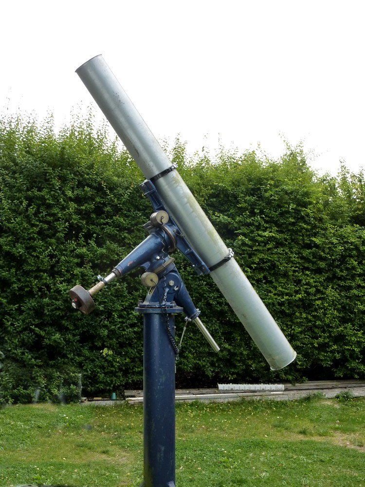
An image of a 2m x 160mm tube mounted on the MkIV on its massive pier. A comfortable balance of scale for a 6" f/12. The MkIV has 1.25" shafts and 2' long saddle. Fullerscopes sold their 6" f/13 refactor on the MkIV. Considering the MkIV was sometimes used for heavy 16" reflectors it should be able to cope easily with a classical 6" refractor.

The diameter of the PVC bearing surfaces will dictate the degree of resistance to movement applied at the eyepiece. Fortunately pipes readily lend themselves to concentric construction. If a 4" pipe moves too freely then make it a 6" with a spacer ring between the two diameters. The ring can be cut from plywood, using a lathe, a router or even sawn out. Electric routers are available for very little money these days. Add a circle jig and an accurately concentric ring scan be cut out in a few minutes.

Want even more bearing resistance? Then make your bearing diameters even larger. Short stumps of PVC pipe should be available somewhere. Even if you have to ask the chaps laying pipes in the road. Pipes get crushed regularly by contractors machines but sometimes leave enough to make a bearing, or three. Short stumps are considered scrap and may even be burnt on a bonfire! Check if there is a well-boring company locally. They usually have masses of pipe of every imaginable diameter [and colour] which can be cut off with a hacksaw or even a carpenter's hand saw. You can tidy things up when you get home.

If  bearing pipes are not readily available then make your bearings out of plywood disks and wrap them with Formica counter-top edging strip. Only testing will dictate the diameter you need for the applied load on the bearings and the leverage you can apply at the eyepiece. Do not underestimate the latter. That foolishly long telescope tube can really be your friend in applying fine and smooth, hand control. With the right construction there will be no familiar oscillations. As the OTA moves effortlessly instead of the jerky snatching of an overloaded commercial mounting struggling to control your long OTA.

The mounting wants to be well triangulated or box-like in form to resist flexure of your chosen materials. 18mm or 3/4" waterproof, exterior plywood is popular and will last for years if painted and protected from the worst of the weather. Spacing the bearings well apart is always a useful ploy to avoid rocking and play. Your greatly expanded axes won't flex so don't introduce play elsewhere by trying to make everything too compact. Well spaced bearings don't throw heavy local loads on the construction. Small mountings have to be made of metal to resist local flexure. Your massively overgrown variety has no local loading to worry about if you design and build it well.

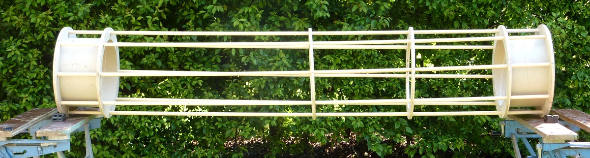
An image of the MkIV carrying a 20cm x 2m [8" x 6'6"] tube. I have had to order some 20cm/8" rings so had to make do with cord for this image. The scale still looks reasonable for a 180mm/7" f/12. Though the MkIV now seems to have shrunk even without a long dewshield on the 'OTA' mock-up. With a matching 27" overhang, on either side of the saddle, the ground clearance is 37" when pointing at the zenith. A bit low, but not impossible to reach, from a normal height, kitchen chair when an eyepiece is fitted in a star diagonal. It would be much more comfortable with a lower seat or 4' ground clearance. Which would mean raising the MkIV 30cm/12" from its present height. Most easily achieved by standing the pier on 12" high foot extensions. Or making  a massive plywood box for the MkIV to sit on top of the present pier flange.

The problem is that the pier is so heavy that it is all but immovable from its present spot. So it would not give me the portability I crave for whole sky observation. Perhaps the answer for the MkIV is a very tall wooden tripod built of substantial timber. Metal is prone to vibration but wood damps vibrations rapidly. Tripods are a bulky method of avoiding flexure in the support for the mounting and the legs often get in the way when viewing overhead.  They are also incredibly difficult to move with a heavy mounting and potential 30lb OTA sitting up on top!

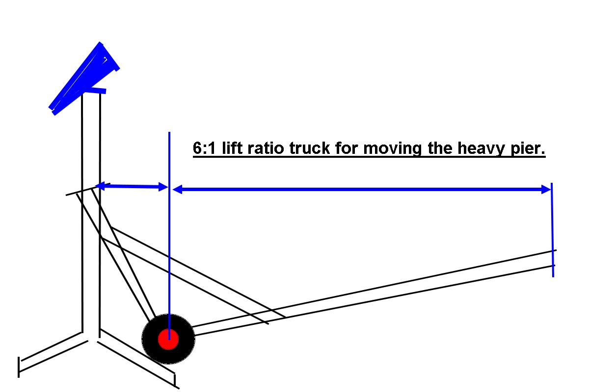
A form of over-sized "wheelbarrow" using puncture proof, barrow wheels could lift the whole pier vertically. It would need very long handles [for leverage] and a very high lifting point to avoid all risk of tipping during movement. The pier + MkIV + OTA could then be moved around bodily to a new site as demanded by the object under study. Moving the MkIV between several permanently installed piers is a complete non-starter. It is far too heavy on its own to be handled that way.

Several piers equipped to take a plywood "Berry" offset fork would work best. The OTA can be "simply" lifted out of the altitude trunnions. The bare fork is then carried over and dropped onto the next pier, the OTA replaced in the fork and one can continue observation. How likely is this to happen in real life? Better ask somebody who could get away with planting several 8' tall steel pipes in large concrete blocks in several places in a rural garden.

On the same subject: Steel pipe piers set in concrete want to be up to the job because they have to be so tall to mount a long refractor. Leverage applied by the OTA to the mounting, or by the wind to the long OTA, will easily find the flexure point of a slim pier. My old, 6' high x 4" diameter, steel pipe pier was far too heavy to lift comfortably but still flexed just above the ground in the slightest breeze. The stiffness of a pipe rises as the square of the diameter. If you decide to use a pipe pier then make it at least 6" in diameter and preferably thick wall.

I just hope you have the clear view of the sky to make the most of where you sink it into that huge block of concrete. Too small a foundation will turn the instrument on its mounting into a compound pendulum. Look up "compound pendulum" online and be very afraid! You may think that filling the pier with concrete would help but it will only lower the resonant frequency of the oscillations. So don't stint on your pier pipe nor the foundation block!

An alternative to a tripod is to make the entire mounting into a tripod. English Yoke or Cross-axis mounting, anybody? The Yoke provides by far the best support at the cost of sheer size and difficulty of transport. Like a fork mounting, it offers support to both sides of the telescope tube. All the bearings are widely spaced for maximum rigidity and lack of play. The length of the yoke arms will be dictated by the length of the OTA. Unless you want a large circle of the north polar sky to be inaccessible then the tube must fit inside the yoke when pointing north.

The cross axis is  like a German mounting but with greatly extended polar axis. The north bearing can be a simple Teflon/PVC pipe bearing. The south bearing can be the same but will want some low friction, end resistance. A single bearing ball, or pointed pin, in a suitable retaining dimple will often suffice. A seriously heavy mounting can use a junk, taper roller bearing.

The downside of the Cross-axis is the need for a counterweight. Though this can be applied almost literally anywhere along the extended polar axis. It need not be directly opposite the telescope tube. Like it must usually be in a compact German mounting. Getting the counterweight out of the way provides much more room in a compact observatory. Walking into the counterweight in the dark is not a pleasant experience. Even worse is standing up under it! The very long polar structure of the Cross-axis allows the counterweight to be placed permanently out of the way. Either down at the southern foot or above the observers head at the north bearing.

A hybrid of the Yoke lifts the OTA above the yoke to allow full polar access. This also requires counterweights to balance the OTA assembly. There are offset equatorial forks too which will also allow a long fork mounted refractor to access the Pole. Again, the necessary counterweights can be fitted at either end of the extended polar axis well away from the observer's likely need for space around the telescope.

The main problem with  these more exotic mountings is the need to provide ground and support clearance for the observer at the eyepiece. With a long refractor this can mean a very tall north bearing support and very long yoke arms. Or an even longer polar axis for a Cross-axis. Moving a Cross axis or Yoke is probably as difficult as a MkIV on a pier. There is no natural point to lift the whole construction however light one might manage to make it.

Allowing the observer to sit on an adjustable height, observing chair will reduce the required scale quite dramatically. Particularly when  compared with having him, or her, stand while observing at the zenith. Reducing the eyepiece ground clearance offers major benefits at most other pointing altitudes too. The use of a star diagonal is taken for granted at higher pointing altitudes but may force the use of a ladder at others. The straight-through view may well be more appropriate at lower pointing angles of the telescope tube.

Try facing the stepladder and looking over the top rung, or around the side. This is often the most comfortable and safest way to observe when you really do have to be off the ground. Don't ever use a flimsy "indoor" stepladder. Builder's stepladders are tough and don't flex and often have extended crossbars joining the feet for greater stability. The folding/locking variety are both cheap and stable and have seriously big, rubber feet. Useful for those bumpy lawns and when snow is lying. Moving them around slightly, to find the most stable position will usually provide a safe perch out in the darkness.

You really don't want to be found lying, frozen solid, perhaps a week after you fell off, because you were observing alone on a shaky ladder! An indoor [domestic] stepladder will sink into the grass, gravel or soil and flex all over the place through piss-poor design and dirt cheap material choice. I have fallen off them enough times to be something of an expert and that was in broad daylight while picking apples!

Having read all this you way wonder why you'd want to reinvent the equatorial mounting when a "Berry style," offset/counter weighted, altazimuth fork is so easy to set up and use. Well, if you are really clever you could become the next John Dobson in equatorial refractor mountings. He broke the stranglehold of heavy equatorial mountings on large, reflecting telescopes. His quiet revolution can still be seen in ever-larger, amateur instruments. Now pushing well beyond the 1 meter / 40" scale. All rely on his sliding bearing principles to support unheard of apertures in deliberately portable form.

Instrument sizes which were once only found in great observatories are now regularly carted around the countryside, for hundreds of miles, in quite ordinary vehicles and set up in fields and parking spaces to share the views and increasingly rare, dark skies. Lightweight, fast mirrors became the norm. As did truss tubes and multi-point, mirror support cells. There are now far more company's making telescopes and their vital components than at any time in the past. Sophistication in design has revolutionised component choice. The startling astro images produced by clever amateurs have long eclipsed those of the professional observatories of only a few decades ago. It takes a multi-million dollar, orbiting satellite with a full instrument platform to provide similar images today. Who knows where amateur imaging progress will lead as computing power, clever software and optical sensors follow a steeply climbing path towards the stars themselves. 

Meanwhile, refractors have hardly been touched by Dobson's great sea change in ATM. A six inch, long focus, "classical" refractor is still considered a huge instrument and remarkably few affordable, modern, commercial, equatorial mountings can possibly cope. It's not just a matter of shaft  size but controlling the moment arm of the heavy refractor lens in its cell on the far end of a 6' or [much] longer tube. Which usually means fitting large enough wormwheels to provide the necessary torque and vital braking forces of that huge, unwieldy tube. If you demand compactness, lightness and portability too, then [quite literally] it "doesn't compute!"

The trend to short dovetails on mountings does the refractor no favours at all. The long refractor tube wants to be supported on sturdy, widely-spaced rings from a long and rigid saddle fixed firmly to a really massive, declination axis. The rest of the commercial "dinky toy" mountings and their tripods may cope with a tiny APO but not much else. Many imagers now use motor driven focusers to avoid contacting the OTA. Portability and Goto have become the hype factors in commercial mounting choice. Or, to misquote the popular Irish expression: [If I owned a "real man's" refractor] "I [really] wouldn't start from here!" ;ø)
 
*

19.8.15

7" f/12 iSTar refractor 1: Toobs

*
While working on the OTA of the 10" f/8 I came up with a surprising number of tube options. Some of these could easily be carried over to refractors:

I used a spiral wound ventilation duct on my 5" f/15. The appearance is very much a matter of taste but the tube was surprisingly stiff and fairly light. I thought it was all I could get at the time. I was wrong:

The alternative from the same ventilation materials source is the straight seamed, galvanized, steel duct. I managed to find one today lying outside a woodworking factory and the weight seemed not too bad at all for a 2 meter, 6'6" length of 160mm 6.3" diameter. The thickness is around 0.6-0.7mm millimeter. [0.025" = 1/42"]

Lindab - LRTR straight seamed ducting.

These straight seamed tubes come in a large range of sizes with matching joints just like the spiral duct variety. There should be a tube size to suit many refractors where aluminium tube is expensive or unavailable. It certainly beats cardboard or PVC drainage pipe for stiffness and probably weight too. PVC bends over time, particularly when it is warm and it holds a lot of heat.

The table alongside shows the LRTR ducting dimensions and weights in metric terms and is borrowed from the Lindab online catalogue. Note that this tubing is available in up to 3 meter lengths. That's 12' in old money. It usually has a small flare on each end for joining tubes in series with a simple clamp. The flare can be utilized as a physical retainer or sawn off to taste.

Provided the seam was placed above or below the normal orientation on an altazimuth mounting these ducts make an attractive telescope tube. Being galvanized means it wont rust easily but it will probably need a special primer coat before painting externally. Though a good example, without too much scuffing, looks well enough in the natural silvery-grey, metallic finish. I doubt that priming  matters much inside where a coat of matt black paint is protected from the weather and won't get physically knocked about.

The ends of the spiral tubes do need cutting carefully to achieve a perfectly square end devoid of jagged edges. I turned a plug from solid aluminium alloy for the tailpiece of my 5". The very thin steel does not have enough "meat" to take tapped threads for screws. The spiral ducts are usually fixed to their joints with self-boring, self-tapping screws.

I cycled 50 miles in vain yesterday while desperately trying to find a straight seamed, ventilation duct stockist in the city. Then discovered a local woodworking factory had some spare, but used, dust extractor pipes. So I am now the proud owner of two x 2m [6'6"] lengths of galvanized pipe at very reasonable cost. One tube of a nominal 160mm bore and the other of 200mm internal Ø. Weighing 13lbs-16lbs respectively.

They are certainly much prettier than the more common spiral wound variety. Both ends have a small, neat flare where a specially profiled clamp would be used to join tubes together, in series, to make any desired length. These flares provide extra stiffness at the open ends which is probably well worth having. The longitudinal seam is very nicely formed and really not too much of  an eyesore when you get used to the idea. The seam is low and narrow enough to be easily lost at the hinge or clamping point of many common, telescope tube rings.

The popular aluminium irrigation pipe, often used for refractor ATM in the USA, is probably heavier than this steel duct due its greater thickness. The nominal stiffness ratio is 3:1 in favour of steel over aluminium. These steel ducts are 0.6-0.7millimeters. [~1/40th"] So the steel ought to be about as stiff as the typical 1/8" [3mm] aluminium irrigation pipes. Local availability will dictate price comparisons. I paid pocket change for mine. The quality and finish of the welded aluminium, irrigation pipes available in the USA seems to be a matter of luck. Freight charges within the USA sometimes seem to exceed the cost of the tube and also makes them vulnerable to damage! 

I now have the option of making a 6" f/12 or a 7" f/12 refractor with plenty of room to spare for properly ventilated baffles. The 2m lengths of 12", 30cm tube felt just a little too weighty @ about 20lbs for my 10" f/8 mirror. Offering no real advantage over lighter alternatives. The image above shows the two tubes exactly as obtained. They should clean up nicely with very little effort.

Many refractors have main tubes of about the same diameter as the lens aperture. This makes for very thin light baffles just behind the objective. Which leaves no room for ventilation holes to avoid air flowing down inside the baffle's central apertures. Where the difference in refractive index with air temperature will directly affect the light path. The best arrangement is probably scallops cut out of the periphery of each of the baffles. Allowing cold air to flow down the inner tube wall unhindered and without affecting the optical homogeneity of the light path for which refractors are justly famed.

Interestingly, Dave Trott of folded refractor fame discovered that air currents were best excluded from his folded 6" design. He went to the trouble of sealing all the casing to stop air movement. I presume his focuser was given the same sealing treatment. I discovered the Vixen focusers are anything but airtight. They allow a constant rain of dust inside the OTAs when standing on their noses. 

The 8" tube looks rather "tubby" despite its quite considerable length. Only if it were stretched to an F/15, or even more, would it probably take on the classical refractor look. Though it should be remembered that the "classical" length of dewshield will add its own grandeur to the overall scale. A self-rolling, black, 'memory plastic' dewshield will avoid adding any extra weight at the "wrong" end of the OTA.

Many modern refractors are already far too "nose heavy" without adding a decent length of metal dewshield. Which usually means the tailpiece/focuser end of the tube far too long below the mounting saddle [or dovetail]. Which further exaggerates the problem of eyepiece ground clearance and forces even higher piers or tripods on longer focus instruments.

Despite their short focal lengths many of the "stumpy" 6" f/8 Chinese refractors were ridiculously unbalanced due to the heavy lens, cell and abbreviated dewshield. Making access to the eyepiece almost impossible when the OTA was pointing overhead on a typical Chinese tripod. Adding a ring counterweight, at the focuser end of one of these refractors, just made the OTA even heavier and increased the moment of the entire instrument. [Moment = mass x distance from the fulcrum or pivot.] Which makes equatorial mounting choice very expensive if the "wobbles" are to be completely avoided. The problem is usually one of very low frequency oscillation taking too long to damp down. The wobbles are usually excited during focusing. Ironically, it is the shorter but heavier APOs which most suffer from this because of their very short depth of focus.


125mm, 5" f/15 beside the 8" 20cm x 2m tube for scale.
N.B: The 5" has 12" of dewshield extension in front of the lens.

The poor, old, classical refractor has even more problems due to its much greater length and inevitably higher moment. Often the "leverage" of the OTA will completely overwhelm the most popular and affordable mountings of today. They are simply not suitable for a number of reasons. The scale is usually completely wrong for a long OTA with the really heavy "bits" at the extremes of the very long tube.

Most refractors, in the past, were housed in domes for the protection of the inevitably massive, cast iron and brass mountings. The main tube was often made of riveted steel since weight hardly mattered. They were never designed to be portable. In fact a ponderous movement was much admired as a sign of quality. Traditional domes do have seeing problems as warm air flows out of the open slit. Particularly when the dome is crowded with people on an organized visit. Roll-off roof observatories reduce such problems at the expense of a serious lack of shelter for the observer and dewing of the instrument.

Fortunately the "Berry style" offset and counterbalanced fork provided an easy and inexpensive alternative to the historically massive, equatorial mountings. The Berry mounting can be cheaply made out of timber and plywood but at the expense of it being "only" an altazimuth. Fortunately, motor-driven platforms can now provide "equatorial drives" if required. These were mainly developed for large Dobsonian Newtonians. Though these clever, motor driven platforms have equal application to larger refractors if suitably adapted with stability in mind. Possibly best applied just below the offset fork bearing plate, rather than carrying the entire tripod or pier. Which is likely to cover a considerable area of ground to stabilize larger refractors.

I made a Dobsonian inspired equatorial from 3/4" plywood plates, several decades ago but it suffered from high friction. The tube and declination axis were too overhung for comfort and required a high torque on the central polar axis pivot bolt. A Dobsonian reflector relies on gravity and the entire mass is over the ground board so only a central pivot pin is required.

The tube of my 5" was made from two, glued layers of 1.5mm rolled marine plywood on baffle formers. A PVC push-pull focuser sliding in a 2" black PVC extension was used. Simply because the thin plywood only came in 1.5m x 1.5m sizes and the focus was 75" or 1.875m. 

Since that mounting failure, I have often considered a "German" equatorial using PTFE/Teflon bearings running directly on massively over-sized pipes for axes. Conventional plumber blocks and solid shafts add enormously to the weight of a mounting without necessarily adding much stiffness unless the shafts are made seriously large in diameter.  Which only escalates the weight problem further.

Thin-wall, larger diameter pipes riding against Teflon pads in plywood housings could just as easily replace the heavy, cast, bearing housings and solid shafts. Easily achieved for a polar axis but controlling end float requires more careful thought in a declination axis. An offset fork with captive Dobsonian bearings could easily take care of that problem but would require an offset counterweight. Spring loading the bearing caps would avoid tightness through imperfect roundness of the large diameter PVC declination axis surfaces.

A suitably large spring to go over the declination pipe, to resist end loading, would be hard to find and even harder to make. Smaller springs working against Teflon pads on a part of the declination axle/structure should work. Equal friction/resistance for all pointing angles is the desired goal. Friction will normally change as the OTA rests all its weight above the polar axis 'T' structure compared with a horizontal declination axis. The traditional English Yoke mounting would suit Teflon against plastic pipe bearings to perfection. The north bearing could even become a thick-wall plastic pipe to allow access to the North Pole. Much easier than adding a "horseshoe" with its attendant concentricity requirements. The Yoke spaces the north and south bearing far apart to reduce flexure. A mounting only needs ball or roller bearings when it is made compact for portability.

The Berry offset fork mounting for refractors provides superb balance between friction and freedom of movement. Only around the zenith pointing angles does resistance to OTA movements rise dramatically. This is only due to the loss of leverage when the OTA becomes parallel to the vertical axis. At all other pointing angles my 5" f/15 moved with an equal and delightfully light force in any direction. From distant memory I think the force required was only was only about 1lb. I used a small spring balance to confirm this at the time. In a fit of desperation I raised the fork tines to compensate for the lack of tripod leg length. Beggars can't be choosers when the scrap heap provides such rare treasures. Most builders seem to keep their forks rather shallow but extend them forwards to take the counterweight without the risk of flexure in the fork structure. 

From memory I used a 6" PVC drainage pipe for the altitude bearing surfaces. The three PTFE azimuth pads were probably pinned on a 6" circle supporting a disk of Formica. A lead counterweight, on a 2" alloy extension pipe, was fitted first and removed last prior to every use. This was to avoid the fork tipping under the weight of the 6" PVC main tube. I should have used a captive bolt and wing nut since I usually removed the fork to bring it indoors to protect it from the weather. The metal tripod stayed out of doors.

A 2" prism was permanently fitted inside the tube on a 3 point adjustable cell with a simple brass push-pull focuser with RAS thread. I only had two simple lenses for eyepieces back then. Though dismantling my utterly useless Dixon's Prinz binoculars provided a better eye piece @90x including a spare for the PVC, 10x50 finder using the Prinz objective. 2" plumbing pipe fitted the tapered objective housing perfectly. The scaffolding poles lacked torsional stiffness where they joined the azimuth baseboard despite the heavy alloy angles which I had used to hold it altogether. My suburban garden was heavily lit by a multitude of street lights! I made the achromat myself from BK7 & F2. It all seems a very long time ago now!

Click on any image for an enlargement.

*

8.8.15

10" f/8 As you were [again]!

*
Having failed to obtain sufficient tube stiffness with the dowels and rings I am back to the alloy beams:
Rather than completely waste the [dowel-drilled] birch rings I made rectangular holes for the beams in a couple of them. Sawing with an electric jigsaw and filing smooth produced a very rough finish. With ragged edges where the top veneers splintered badly. What was worse the holes had almost no sizing tolerance. The beams either went through the holes or they did not. And, if they did they were too loose on the beams. With no means to fix them other than bolting through the beams and cardboard cells. This seemed just too crude for my liking. Plus, I really wanted an infinitely adjustable, sliding/clamping fit for the cell along the beams. The clamping was the difficult part if it was to be foolproof without becoming an eyesore.

A plywood ring does not readily lend itself to a clamping action on a rectangular beam lying within its concentric depth. I imagined cutting a slot inwards, from the perimeter to the rectangular hole. This would allow some free closing movement in the otherwise rigid plywood. Cutting outwards from the ring bore to the hole would raise a struggle between the the plywood ring and the glued cardboard tube. I need that joint to be strong to ensure the stiffness of the complete OTA.

Applying pressure, perpendicular to the slot, raised a number of possibilities. "Ears" could be formed on the ring's perimeter to accept a clamping bolt. Though the plywood is really too thin to be drilled on edge. Besides, the "ears" might catch on things including cloth shrouds. Eye bolts, fixed through the plywood rings with clamping bolts through the "eyes" offered another possibility. Or, blocks of thicker plywood glued and screwed to the sides of the rings with compression bolts between pairs of blocks. That might work but might also be very ugly if not made to a suitably high standard.

The eye bolts sounded like an easy option if only I could ensure they remained rust free. The usual 'flashy' zinc coating doesn't last long once the retail bubble pack has been brought home and opened. Stainless steel eye bolts might be hard to find outside a boat chandler. Finding some brass eye bolts might be possible but they would need to be of thick enough rod to be stiff enough.

I was really hoping for a universal and cosmetically attractive solution to the beam clamping problem. One which could be imitated across a wide range of  OTAs based on beams and plywood rings. Including refractor OTAs if at all possible. Though the rings need not be circular on their perimeter the inside "hole" would he wasted if it were not also made into properly sized baffles to increase contrast. The smaller the baffle hole the heavier the ring simply because less material would be "missing" from the middle. It might be better to go for a standard 12mm plywood ring and then add thin baffles from a suitably light, sheet material. A refractor should ideally have metal baffles, anyway, just to avoid starting a fire with unfiltered sunlight!

My cutting out of the rectangular holes for the beams needs to be greatly improved. Using the router might be a much better option. It just needs a suitable jig to ensure an accurate and neat hole every time. Though the corners would need a different approach.

I have become rather fixated on the cardboard tube and two rings type of cell. I could easily change tack completely and make sliding boxes which clamp onto the beams. I saw in interesting variation on the beam/spar type of OTA on the iStar Scope Club forum. This used a wooden spar situated underneath adjustable, right-angled cells. So there is plenty of room for inventiveness around the basic beam/spar idea.

At the moment, I am gently steering myself towards shallow, three-sided plywood channels. These channels would be set-in and glued  into the opposite edges of the rings to join the two rings to make a cell. With the present 30cm cardboard tube also joining the rings for extra stiffness and reinforcement. Though this may not be necessary if the plywood channels provide enough stiffness on their own.

An overlap of the plywood channel, beyond the enclosed beam, will allow a clamping action at its outer edges. The channels will slide smoothly along the beams but still be able to clamp anywhere along them using a T-nut and long bolt. This bolt will span between the top and bottom of the channel, outboard of the beam and apply pressure on demand to the tops and bottoms of the beams.

The present arrangement, seen in the top image above, is far too difficult to slide along the beams without the holes being made unnecessarily oversized. Nor is there any easy way to fix the complete "cell" to the beams without boring holes for screws or bolts.

The lower image shows how the inset [box] channels will appear from above the ring. The colours are supposed to represent the plywood channel with the enclosed 100 x 18mm, rectangular, tubular beam in the centre. [Centred on the redundant dowel hole.] The two shallower sides of the box channel will extended slightly more towards the camera. This will allow room for the clamping bolts to safely clear the beams to avoid cosmetic damage. Though the screws could be covered in plastic tubing. The plywood channels can be easily formed and glued around the beams with polythene packing to ensure fit and squareness. Once the glue is dry and the packing is removed the sliding fit should be perfect.

The advantage of this arrangement is being able to carry it over to any other OTA. Rings could be replaced by squares or rectangles of plywood baffles in smaller OTAs and refractors. Further tubular beams could be introduced to the top and bottom of the "tube" for extra stiffening on equatorially mounted OTAs. Or even a triangular baffle arrangement, like the iStar TCR lightweight refractors, is also, easily achieved.
*

3.8.15

10" f/8 Caging the 10" f/8.

*
After much searching I have found a nearby stockist of Birch plywood including the desired 12mm. Not cheap but excellent quality. BWP B/BB. I'm taking the trailer out tomorrow to collect a 1.52m x 1.52m sheet of the 12mm to make some more and better support rings. Their thinnest is 4mm but I'm not sure what I could use that for. Probably too thick to make knife-edge baffles for each support ring. Now the weekend weather is committed to gales and very heavy, thundery rain as a low passes over. I shall have to wait for next week to collect the new plywood. No point in it getting sopping wet, or even blowing away, before I can even use it.

Returning to collect the 12mm Birch plywood proved that it was mislabelled. Fortunately an 8'x4'  sheet of old stock was hiding underneath. As I was given a discount for cosmetic appearance, I accepted the very dusty exposed side and took it home. Birch plywood is incredibly dense and heavy at 700+kg/m^3!

I'm still practising on scrap 10mm in getting exactly the correct diameter to perfectly fit the cardboard tube. Once I had thought it through it was actually quite easy to cut a ring. First I made a slightly oversized 1/8" [actually 3.2mm] central pivot hole in the plywood. Then I cut the outer circles first from both sides of the plywood. Until I had just broken through on the second side. Using the router's stepped, depth stop safely avoided going too deep and cutting into my workbench!

I just had to be very careful with the very last bit of each full arc. Then I reset the radius jig and started with a first shallow cut on the inner circle. After repeated increases in depth from both sides this removed the inner circle from both sides of the sheet to leave a neat ring. Again, I had to take great care over the last inch, or so, as the scrap material became loose. The friction of the plywood on the working surface was just enough to keep it still while I swung the router gently around the pivot pin in the circle cutting jig. It is impossible to clamp the material without using pins or screws because the router or circle cutting jig will surely strike the fixing.

 I have now paused on the twin beams design and shall build an 8 dowel, 8 ring, skeleton tube next. Just to see how stiff and strong it feels. I shall use short 8" or 20cm lengths of cardboard tube to act as the stiffening cells for the primary and secondary mirrors.

 As it will be an altazimuth design the skeleton tube will be evenly supported from either side by the altitude bearings. Which is not remotely as locally stressful as hanging the entire OTA, from one side only, on a declination axis saddle of an equatorial mounting. If the 16mm dowels prove too weak, to hold optical collimation with changing altitude, I can always exchange them for aluminium tube. Though I doubt there'd be much difference in overall stiffness unless I seriously increased the diameter of the metal tubes. AE of the UK used a very attractive, all-aluminium skeleton tube design for some of their telescopes. Though those were really intended for their excellent equatorial mounts. Bath Astronomical Society had a 10" AE in a dome in the secretary's garden. A lovely bit of kit but well beyond my means, then and now.

I have now removed my DIY plywood circle cutting jig and now use the original router fence bars with a piece of alloy angle to hold the centre pin. Again, I used a T-nut with the spikes cut off to allow plenty of thread length for holding the centre pin really firmly without increasing the height of the pin assembly below the alloy angle. Once I had the exact radius settings for the circle cutter on the router I was able to produce 6 rings quite quickly. The secret was to cut the outer circles first from both sides until the disk parted from the sawn square. Then I cut the inner circles [again routing in increasingly deeper steps from both sides] to cut out the centre circle to finish the rings. I was using an 8mm bit because my 6mm had broken on an earlier project and I had lost its replacement. Sawing out squares from the 8'x4' sheet ensured the maximum ring size without cutting into each other where they joined. The router bit would overlap the intended circles if I had routed the rings straight from the whole sheet.

Now I will need to fix the rings together with register pins. Then drill them precisely for the eight dowels to the pattern I drew on the first ring before it was cut out. I made the rings as large as I could within the 4' width of the sheet of plywood. Which made them just under 16" in diameter. I need not have worried about slipping the mirror cover between the dowels of the cage. There is plenty of room to fit a hand between the dowels.

Drilling the rings with an initial 3mm-1/8" drill went smoothly thanks to the twin coach bolts I set up on the cheapo drill table to help centre the rings. With each new hole bored through the master ring pattern I dropped a galvanised nail into the drilled hole. This kept the position of all the holes identical in the rings lying underneath. In fact it went remarkably smoothly as I numbered and edge marked each drilled circle to ensure they would all match. After that I cold bore the 16mm holes, with a pointed, spiral bit, with full confidence that they would all lie exactly over each other.

I was just going to trial build the cage, for a photograph, when I discovered that the dowels varied slightly in diameter! They were all bought at the same time and from the same DIY superstore. They have also been standing vertically in a tied bundle in the workshop for literally ages. So they must all have equal [and low] moisture content.

I will now have to measure their individual diameters with a vernier calliper and sand them to a suitable size to slip easily through the rings. Gluing will hold them safely even if there is some slight slop. This will help get all the rings more easily onto the dowel cage. It's a shame because the 16mm spiral bit was rather expensive! It was purchased for this one project just to ensure greater accuracy than using a normal twist drill, or even a spade bit. Trying to build the cage with such tight fits is all but impossible! However tempting it might be, I am not driving the 20 miles to check their present dowel sizing to find replacements!


The dowels proved to be slightly oval and sanding had no effect. By sheer coincidence I had a ball shaped bur which would produce a nice hole provided it was used at very low speed. Assembly went rapidly after that. As can be seen in the image above. Now I need to provide a primary mirror cell and fit the focuser, spider and finder to get some idea of the longitudinal balance point. Weight, as seen, is 5.55 kg or 12.3 lbs. The bare cardboard tube had weighed 22lbs or 12.5kg! So nearly a halving in weight for the dowel and ring design. Gluing the thing together is going to be fun!

The problem is that gluing is unlikely to increase stiffness by very much. Just glancing along the leaning OTA showed significant droop. So I spanned the distance between two workbenches to see the "tube" sag even more! I took the image from some way off to counteract any barrel distortion in the camera. Supporting the OTA from somewhere near the middle would probably halve the sag visible here. Higher altitude angles would reduce it even further. I still don't think it would help much. This long focus design is a complete non-starter with only 16mm dowels. This is without the extra weight and moments of the optics and their supports at each end. Alloy tubes might be stiffer but not by much in this relatively small diameter.

Lesson learned, so now it's back to the alloy beams. With only 1/3rd of my sheet of 12mm Birch plywood wasted on the pointless rings. I don't think they will serve in the simple two beams approach because of all the bored holes. I will have to look into this in case they can save some time and recycle the wasted materials. Short bridging dowels may offer increased resistance to the rings twisting despite the cardboard tube reinforcing the cells.

Click on any image for an enlargement.

*