*
When it can't see the sky?
Here is another random, scatterbrained discussion of my difficulties in overcoming a lack of clear sky. Our house runs along the southern border of our rural property. There is a shelter belt of trees to our west. The northern and western borders of our garden are also wooded for all intents and purposes. Our eastern border has an 8' hedge and another 8'+ hedge on the far side only a few yards away. Lifting myself and my telescope by 8' from the ground gives a remarkably improved view of the sky except to the north and west. The lower altitudes are hardly worth having anyway due to much poorer seeing. I have always tended to set up on the parking area north of the house. Several large trees stole my view from the main lawn over the years as they rose by at least 20'.
I am still struggling with the problem of improving the OTA balance
point while avoiding adding unwanted mass at the focuser end.
Observatory telescopes often have added weights but I am not supposed to be building
such an instrument. This OTA is supposed to be light enough to be fitted and removed from the hinged
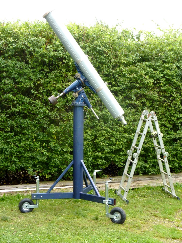
mounting rings by one person. Recently, I watched three men, lifting, moving and mounting a modern, commercial, 8" refractor OTA on a YouTube video. Whoah! I am past retirement age and would be working entirely alone under much more difficult conditions!
What about a crane? A boat winch attached to a simple frame built rather like a garden swing? It need not be very heavy but could have wheels to bring the OTA to the mounting. Except that a fixed mounting is so limiting down at ground level.
I could make a waterproof "roof" for the complete telescope but worry about rapid deterioration. A lens cap would keep
the worst of the weather off the precious objective. While the OTA rests horizontally and permanently on its mounting under its minimalist cover. But! I already have birds nesting in the MkIV mounting under its closely wrapped and tightly secured tarpaulin! Imagine what the little devils could get up to with a bare telescope tube under a simple cover? There would be standing room only! How is this supposed cover to be supported? How light can it be made? Who will lift it down? How will it survive a wind storm or heavy snow? A steeply pitched, A-frame shelter could be wheeled away from the complete telescope on its mounting. Back to the poor, sky visibility, ground based telescope problem.
A number of secure outdoor "cupboard" options occur to me but these would still
require extracting and
lifting the heavy and cumbersome OTA onto the high mounting. And, taking it back down again when I
am tired. Probably in the early hours of the morning when it is pitch
dark and the telescope is quite literally sheathed in ice. I thought of a series of hooks or lipped shelves to be fixed to each rung of a builder's stepladder. The OTA could be lifted and lowered in small, secure steps while kept safely horizontal. I could rest at any point in the manhandling of the OTA. The difficulty is in raising myself to match the present height of the OTA so tat I am not lifting overhead.
A carport
or garage would offer decent cover and weather protection but I don't have a carport. There is plenty of room for one but it would add considerably to the expense. Though the raised platform idea is not impossible if built with DIY skills rather than a commercial kit. All of which leaves me torn between several, completely conflicting choices.
I would much rather be observing from the roof of this non-existent
carport. Which automatically demands some kind of totally weatherproof cover for the telescope since it cannot be taken up and brought down again between observations.
Say I built a platform in front of the shed's southerly gable end. The existing shed could
even have rails bolted to the roof to allow a similarly pitched,
lightweight roof to
roll back to uncover the instrument. Except that the rolling roof would
be far too low to cover a refractor on a platform on an even taller
pier. A steeper pitched, roll-off roof would add a little extra clearance height but
might then act as a sail. Let's not forget
about building that sky-scraping pier while we are pondering this
option.
A telescope cover always assumes it is easily removable to allow whole sky views. Isn't that what is usually
known as an observatory? Do you know any carports which have a huge pier right in the middle? The pier would make a mockery of my already limited parking skills. Build the pier in the unused space between two adjoining carports? Yeah, right! Let's double the expense!
Climbing stepladders on a raised platform to fit a recalcitrant tarpaulin? You are joking? It is already a struggle to cover the mounting on its pier at ground level using a sturdy builder's stepladder for support! Now add the spinnaker required to cover a 7' long telescope on that same, 8' tall mounting. With all of the above raised on an open platform without the protection of our own, soaring hedges.
Something to house a 7' long
instrument [with added 2' dewshield] preferably needs completely safe standing and sitting room for the
observer on all sides. All of this raised high above the ground? What
about that incredibly tall and massive pier? Something solid
enough to support the telescope and mounting free of the platform and
the inevitable tremors that is somewhere around 16' high? What about that "something" which can protect the telescope
permanently from the weather. Yet allow rapid access without my lifting
anything heavy nor risking my life?
Better surely to move the whole instrument on
large pneumatic wheels on the ground? Wheels which can carry and move the load regardless of the firmness and flatness of the
ground? [Snow, ice, soft gravel, soggy lawn, wheel tracks and melting permafrost.] Wheel the instrument to
positions in [and out of] the garden where more of the sky can be seen. The fat tyres are easily firm enough to ignore telescope movements and a modest wind.
What about screening from several neighbour's comfort blanket "security" lights and passing traffic headlights? It's much like the contact scenes from
Close Encounters around here in winter. With those blindingly bright strips of "landing lights" left on all night just in case. I kid you not!
I could build huge castors with the wide, 40cm/16" pneumatic wheels which I already own. These
would automatically provide an altitude boost depending on their exact design. In fact, only a single wheel actually needs to be castored to allow steering.
There would then be no need to build a massive wheelbarrow, or cart, to move
the pier around.
Building a practical cart has already proved far more difficult than I ever imagined
after wasting a whole morning with a stack of 8' lengths of slotted angle
iron. The sheer effort required to lift and move the pier with such a contraption
easily outweighs any possible advantages. The same would hold true for a converted car trailer chassis. The ground is not level and landscaping to make it level is not remotely an option. Think in terms of contractor's digging machines and lorry loads of imported sand or soil. It's just not going to happen.
The cost and
disruption of covering the entire garden in concrete slabs, to allow
easier movement on the existing castors, is a complete non-starter.
Rails are similarly out of the question. The area to be covered would require much of the garden, parking space and drive be turned into a paved surface. It would require
attacking the existing trees and tall hedges just to be able to move the
whole pier and its telescope freely around. If I cut down all our own trees and hedges the neighbour's obscuring greenery, and adjoining small "forest," would still be there.
Building a platform in front of the house would expose it to gales, the neighbour's overkill security lights and very public view. Not an option I really favour for all of the above reasons. Though it would gain much more southerly sky despite the high, shelter hedge. This forward position has already been vetoed by the constant gardener.
I could build a temporary scaffolding platform in front of the shed but am unsure how to source such material. Aluminium scaffolding towers are ridiculously expensive and have very small working platforms anyway. Perhaps a few 4"x4" pressure treated posts and some joists and planks is the best answer? Though still leaves me with the problem of the tall pier.
Old TV lattice masts might be the answer here. There is a steady trade in old and new masts in Denmark. Being self-standing [on concrete foundations] avoids the need for guy-lines, massive concrete castings or triangulation. Getting them home might be the biggest problem apart from the weight. They are far too long to simply put on a car trailer. I have sourced an unused mast not far away at an acceptable price but fear the huge effort in setting it up vertically and keeping it that way. These things are deliberately massive, galvanized, solid steel bar and intended to last for many decades without safety issues.
I [we] could move to another house with far better access to the sky. Except that we are in the middle of a continuing housing recession in rural Denmark. The banks aren't lending all that taxpayer's bail-out money to
anybody. Least of all the already retired with no capital and a lingering mortgage. Houses locally have been sitting on the market for years as their estate agent's signs slowly faded to illegibility. There is no reason to suppose anything will change soon. Nor that our own particular "des res" enjoys any greater sales potential than any of the others.
These unsalable homes usually end up on forced auction, even being abandoned or demolished. So that the area becomes an eyesore and drags other local houses further down into the mire. So a quick sale and purchasing elsewhere is as likely as all existing hens growing a smart set of teeth overnight. There is even political talk about dumping the ongoing masses of refugees into empty rural housing. Except that most refugees aren't stopping here but going straight on to Sweden and beyond. They have probably heard about the cost of living here!
Click on any image for an enlargement.
*
 Sometimes the gods of the stars do smile upon us. Perhaps in compensation for missing the Lunar eclipse: I was searching for a suitable rail on which to have a sliding counterweight. And there it was, hiding under the bench in the shed with two neat brackets all in shining stainless steel. It was once a towel rail, I think, but I have absolutely no recollection of buying it on my endless rounds of the flea markets and charity shops looking for ATM materials. I just needed to curve the "feet" and find a suitable weight which would clear the main tube. A delve in the brass stock bin provided a nice sized stump to be bored and turned to make it tidy. I have a wheel and screw borrowed from another counterweight to allow it to grip the rail securely. A plastic plug will avoid marring the rod and make sliding more pleasant..
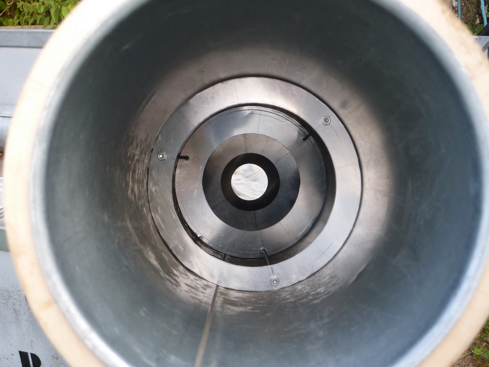
 If I put it in the wrong place it will be more distant from the mounting's counterweights on the declination axis. Which will require some compensation to bring the OTA back into balance around the polar axis. If the weight is fixed too high on the tube it will tend to rotate the OTA when it is being carried. In the end I fixed it below the finder without removing any handles. The problem then was inserting my large hand through the smallest baffle to fit the lock washers and nuts on the inside of the rail post screws. Not quite "blood everywhere" but it required some dexterity to retrieve my hand. There were far too many projecting screws inside the tube holding the handles on. All of which would need removing, with one hand, before I could slide the baffles out to work on the rail screws in the bare tube. The split, lock washers will ensure the counterweight rail doesn't work loose over time.
  With the new tube counterweight midway on its rail a check on the new balance point had it at 80:100cm in favour of the objective. Not too bad really but I'd much prefer a midpoint for a nicely "balanced" look when fixed to the mounting. A short "top end" above the mounting rings always looks wrong to my eye. It's as if the OTA has slipped down through the rings while pointing high in the sky. Which probably means I will have to add more weight at the focuser end. It is much easier to balance the tube on the mounting, with the axes unlocked, rather than resting it on a fulcrum bar on the workbench. The OTA tends to want to rotate on its axis to find its natural balance point. Which means the finder and counterweight try to rest on the bench and won't allow the tube to see-saw.