*
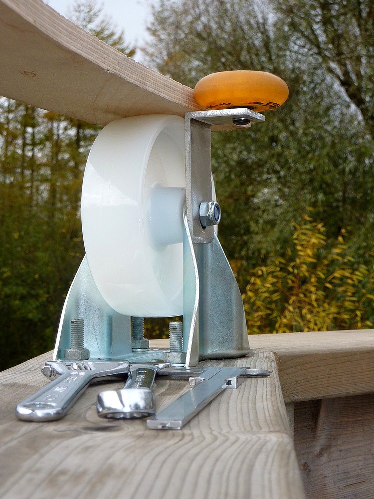
Wednesday: Completed drilling and fitting the shelf brackets to the
main wheel pressings. No bolts to fix the wheels. Another shopping trip!
Bought all stainless steel screws and nuts for the wheels and brackets.
Should have finished the wheels by tomorrow lunchtime.

Thursday: A grey, windy day. Finished fitting the
centering/steering wheels to the brackets. Then found the base ring is
oval. So the ring goes tight on one diameter despite my allowing some
clearance on all the centering/steering wheels. Rain expected after
lunch so I have covered the wheels and taken down the base ring for
closer examination and measurement. By the way: The beer crate is a
handy workbench, seat and step-up stool and does not indicate excessive
consumption. Beer is also an excellent slug trap.
I
arranged the dome base ring on blocks on the lawn and measured it. Then I
brought out the beam compass I had used to draw the initial arcs for the
ribs and base ring. The beam compass was far more useful than pushing
the ring around. With a long screw as a pivot in the lawn it quickly showed where
the radius changed rather than the diameter.
The only
obvious way to progress is to glue the ring's half lap joints with the
ring first made perfectly round. Then to lift the entire ring up onto
the wheels using cross braces to increase the strength of the ring. At
3.2m [ten feet] in diameter the 15mm ring is far too flexible to risk the
lift unsupported.
Should I add another layer of plywood
to the ring for greater strength? I have no idea but don't like the
extra cost and considerable added weight. Carrying all of the base ring
arcs at the same time is hard work! I usually only carry two or perhaps
three.
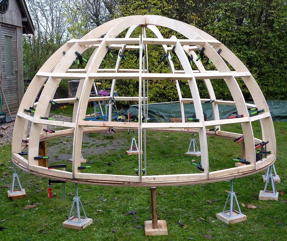
I had hoped the lowest, horizontal, dome braces
would add their
considerable stiffness to the base ring. With the added stiffness of the
dome
structure the ring becomes inflexible. I shall also add horizontal
braces to the inside of the base ring but all that is somewhere down the
road.
Friday: I drilled the lap joint areas to tent peg
the ring to the lawn while the glue dried once perfectly round.
Unfortunately it started raining and became steadily heavier.
Attempt abandoned.
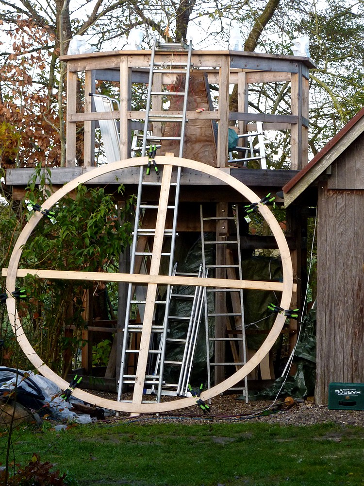
Sunday: Having decided to add another layer of birch plywood to the base ring I drove 10 miles to a stockist. To find they had closed despite the signs saying they were open on Sunday. Grrr?
Monday: Another outing in the car and I brought home another 5'x5' sheet of 15mm Birch plywood. Plus a sheet of oil-treated hardboard. [Masonite] The latter will be added to smooth the surface of the wheel track. The 15mm ply will be cut into arcs and glued to the original ring to produce a 30mm thick base ring. With the hardboard track providing the extra [odd] lamination.

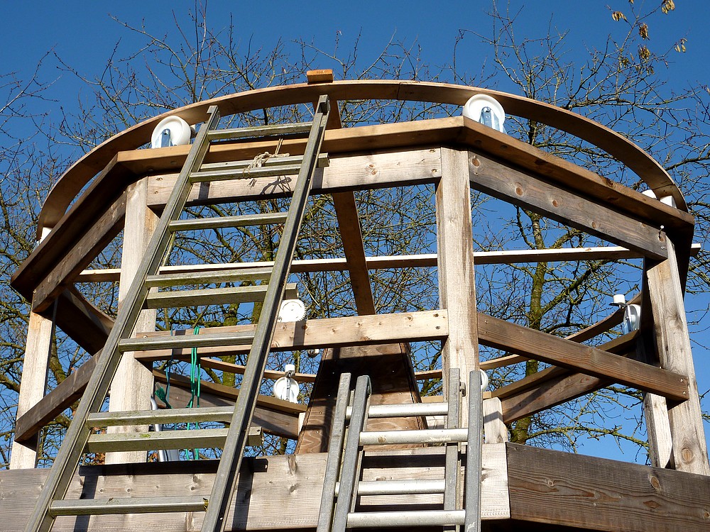
I have been pondering different ways to ensure the ring will be round rather than oval. If I use cross braces the completed ring must be able to be lifted onto the rollers without obstruction. The double thickness ring will not be light enough to handle easily unaided due to the sheer size making it very awkward. Perhaps I can build a lifting jib using the 5m [16'] ladder and the two builders stepladders? The problem is avoiding the ladders causing an obstruction in themselves.
Perhaps a simple inclined plane using the long ladder and the boat winch [or just a rope] is the answer? The inclined plane [ladder] could slide up over the octagonal top ring under the control of the winch. Bringing the supported ring with it. The ladder would easily slide between the rollers and could then be removed when the ring is safely in place. A rubbing strip fixed to the octagon ring will protect it.
My fear is that pushing the bare ring up the sloping ladder would break it when it reached the top and flopped downwards. If I was at the top and pulling a rope, attached to the middle of the cross-braces, I would be in a position to 'field' the ring and lower it safely down onto the rollers from the stepladders.
It gets even easier if I allow another ladder to slide up the big ladder. This allows the bottom of the big ladder to be pulled out for a much more gentle slope. The winch cable can run over the top rung of the 5m ladder and connect to the bottom of the shorter, sliding ladder. The shorter ladder has hooks for the rungs so will be safely locked at regular intervals on the lift should I need to go down and adjust anything. Though the winch does have the usual locking tumbler pawl on a ratchet wheel.
Tuesday: A miserably wet, cold and windy morning clearing after lunch. So there's a possible window to cut the new arcs. And there was. I marked the first arc with the beam compass at 1.5 and 1.6m on the plywood. Then checked with an existing arc to see if both were accurate. I then used the arc as a template to mark seven new 15mm arcs which were sawn out with the jigsaw. Each freshly sawn arc weighed 1.75kg. 15 arcs to complete the whole ring @ 30mm thickness = 26.25kg = 58lbs! Manageable but difficult to handle due to the sheer size.
I have to decide how to join the new ring onto the old. I cut the ends off square on the last one and made half lap joints. It might be stronger to use skewed butt joints on the second ring lamination and stagger the joints relative to the first. The wheels should roll more easily over a diagonal joint. Though I hope to use the longer arcs cut from the 4'x8' hardboard on the underside of the ring to achieve even smoother joints. The birch plywood is in 5x5' sheets so makes shorter arcs.
A contact warned me against having hills and hollows in the base ring's desired perfect flatness. Which would make the ring drag at intervals as the wheels had to climb 'uphill.' Hence the move to a double thickness ring and hardboard running surface.
Wednesday: A promising, sunny autumnal day has now been muffled in thick mist! At least it is dry so I can continue work on the dome's base ring. I shall arrange and glue the original ring together on blocks laid out on the lawn. The blocks can be carefully leveled with a long straight edge and 4' level.
I can use my ratchet straps to pull the ring into perfect roundness using the beam compass to check. The diagonals on one end of each arc of the second ring lamination will be used to scribe the next joint. I shall use the diagonal cuts as butt joints and rely on the lower ring for even support.
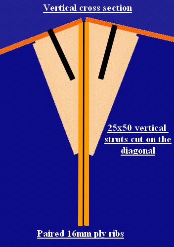
The bottom struts of the dome segments will heavily reinforce the completed 35mm thick base ring. With a second horizontal strut on the inside of each segment, to match the outer one, the ring will not dare to warp.
Click on any image for an enlargement.
*