26.2.17

Compression Mounting: Testing-testing.

*
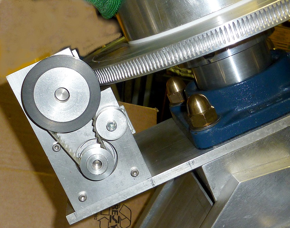
Testing the mounting drives with AWR threw up some obvious problems. The RA motor kept stalling and groaning loudly. I decided this was probably due to the drive belt being too tight. So I dismantled the housing and replaced the large aluminum pulley with the original urethane bush. The motor then turned happily enough. Though slews did seem rather slow.

The Dec drive had no problem turning the worm but the worm wasn't even touching the wormwheel! I had to remove the drive system and make adjustment slots in the main support plate for the fixing screws. I'm not sure how the worm/wheel distance changed from perfect to missing the wheel completely. Presumably this was due to changed position of the flange bearings during re-assembly.

I am working comfortably in the shed now that the temperature has risen to 43F. It was miserable working earlier in the week at 28-34F.

The motor stalling problems proved to be simply a lack of balance. With the wormwheels engaged in their worms it was difficult/impossible to judge the overall balance of the bare mounting. So I just kept adding G-cramps to the saddle until the declination axis was balanced. It took almost my compete collection and I had to disengage the worm to allow the bearings to run free. After that I could re-engage the worm in its wheel.

From that point on there was no problem slewing. From numerous RA slews of 90° against the clock I was able to confirm slightly better than 45° of axis rotation per minute. The Declination slews were slightly faster at 50° per minute. While it certainly looks slow while watching the mounting axes rotate I think 45 degrees per minute is very reasonable. Four minutes to cross the sky from East to West? Not bad at all IMO. Though it should be realised that a long and heavy OTA will have considerable moment. Whether this affects slewing speed I am really not sure.

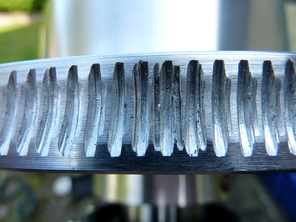
At first I could hear a cyclic grating sound. Which proved to be the RA worm rubbing eccentrically on its wormwheel. The worm is obviously not perfectly true and the mating surfaces not remotely polished. The wormwheel teeth [slots] were very rough and grubby as supplied. I had scrubbed them with a toothbrush to remove most of the debris. Whether it would be safe to lap the worms and wheels together I am unsure.

Beacon Hill's Barrie Watts suggested using only light oil for lapping on his wormwheels. Not to use any form of abrasive. So I added a drop of light oil to the RA worm and it fell silent during slews. Given the roughness of the wormwheel teeth it might be worth using something like Brasso or Solvol Autosol to speed up the polishing action. The worm shaft bearings will have to be protected from abrasive migrating along the shaft.

Beacon Hill quality?

Quote from the Beacon Hill website: "They are the most accurate worm and wheel sets available to astronomers in this country."
  
"The matching stainless steel worms are held in sealed roller bearings in substantial brackets and are fully adjustable to eliminate any developing end float."

In reality the worms are brass and the ball bearings are held in place in their channel profiles by one tiny grub screw and shellac. Over-tightening the grub screw simply stops the bearing from rotating! A retaining plate fixed to the free end of the profile would seem essential. Just to stop the bearings being forced out of their "housings" due to the end loads on the worm.

It took two attempts and two months to get anywhere near the bore size I ordered. [50mm] In a fit of total madness [and growing impatience] I eventually accepted a pair of worms and wheels with 60mm bores. Then made brass sleeves in my own lathe to match my axes to the oversized bores. I was too ashamed at the time to share these images of the absolutely pitiful machining quality. Where else would I get an 11" wormwheel? Except from Byers in the US with the price doubled by freight, customs charges and import taxes!

It would help if the worm was actually stainless steel instead of brass. Stainless steel is very hard to wear away so it would polish the teeth of the wormwheel nicely without damaging itself. Brass? I am not so sure it wouldn't wear more rapidly than the aluminium wheel. How hard would it be to make matters any worse than the images above?

Barrie Watts of Beacon Hill is well aware of the problem regarding his false advertising and shoddy goods and service but has made no attempt to contact me. He continues to blame a very elderly machinist in his employ. Caveat Emptor!


Click on any image for an enlargement.
*

Compression Mounting nearing completion Pt.3. The obverse.

*

With the mounting nearing completion I thought I'd better have a look at the other side. It had been sitting with the same orientation, on its handy beer crate workstand, for ages.

I am staying safe and leaving the tensioned hoist strop in place. Just in case the sheer weight crushes the beer crate.

Adding counterweights was enough to destroy a B&D workbench last time! So I'm not taking any more chances.
This closer side view shows the belt drives to the worms and wormwheels.

Next stage is to connect the AWR system to check if the drive systems can move the axes. I don't have any doubts that it can. The wormwheels multiply the torque by 287 x the belt drives extra 2.4x. A theoretical increase in motor torque of 690 applied to the axis shafts. IT is already impossible to stop the stepper motors from rotating by gripping their pulleys by hand!


The declination drive belt had no need for a tension pulley due to the offset between the worm and motor pulleys.

The large brass sleeve with radial, butterfly nuts will eventually go on en the end of the Declination shaft to retain the counterweights. Here, it is simply retaining the wormwheel.

Another brass sleeve, 10mm wide, spaces the wormwheel from the flange bearing. This distance piece centers the worm on its wormwheel.


Overall view from above. The scrap aluminium plate was mostly in good enough condition to use without serious cosmetic consideration. I have given it a quick rub over with Scotchbrite maroon fiber to tidy it up a little. I expect it will become spoilt by moisture over time.

It is supposed to become a working mounting.


Click on any image for any enlargement.
*

25.2.17

Compression Mounting nearing completion Pt.2.

*

Moving the RA wormwheel to the bottom of the PA shaft was seriously considered and finally rejected. I could have overcome the serious clearance problems but decided it was really only a cosmetic issue.

The sheer scale and weight of the finished mounting has to be experienced to be believed: Just lifting the Declination shaft [with saddle attached] and inserting it into the Dec housing bearings is quite a struggle. The image shows the dimensions in cm. 

The bearing housings are 15cm or 6" square in cross section. 
Total Declination length = 115cm = 45.25"
Height from under base plate to tip of saddle = 110cm = 43".
The PA housing is 70cm long = 27.5"
The saddle is 70cm long x 10cm wide = 27.5" x 4".
The RA wormwheel is over 11" in diameter. 
The Dec wormwheel Ø = 8.5".
The axes shafts are solid stainless steel and 50mm in diameter or just under 2".
The heavy, cast iron, bearing flanges are 143mm or 5.6" square.
The four, corner, tension studs inside the bearing boxes are 16mm in diameter = 0.63".
As is the altitude pivot stud.
The cast iron counterweights are 23cm or 9" in diameter.

I should have called it the Compression Mounting had I thought of it earlier. The axes flange bearings compress the bearing housing plates with the four 16mm corner studs and domed brass nuts. The heavy stud's stiffness in tension is the resistance against which the cross studs and plates are retained. The multiple cross studs compress the 10mm thick plates of the axes bearing boxes against the tensioned corner studs. The cross studs employ furniture, flanged nuts. These have a long thread length for greater strength in tension and the flanges help to spread the compression loads evenly. The Dec axis housing is directly compressed to the large [7" Ø] cylinder.

The Tollok bushes are compressed strongly onto the heavy shafts by opposed, polished steel cones. The same Tollok bushes simultaneously expand outwards into their respective housings. The saddle bush utilizes a very heavy wall brass sleeve to contain the Tollok bush. Which is tensioned and located to the saddle by its 10 x 8mm fixing bolts. While the PA bush sits inside the 7" diameter cylinder. The two are secured together with additional 8mm stainless steel studs. To fix the Declination housing immovably to the large cylinder. The Tollok bush is simultaneously bolted to the nearest 10mm plate by its 10 x 8mm [SS] screws on a large pitch circle. Stainless steel washers spread the clamping load to the maximum possible extent. A far stiffer arrangement than a single large nut, bolt and washer.

These nominal 50mm shaft size, Tollok bushes were deliberately chosen to have the maximum flange size of 90mm. Simultaneously they offer the greatest, compressive sleeve length to resist any chance of rocking on the heavy axis shafts. Once the opposed cones are compressed together, within their enclosing metalwork, they behave as effectively a solid mass of metal attached to the shaft. The major advantage is that they are easily removable by releasing their 10 compression screws.  These steel bushes are commonly used in industry for attaching large drive pulleys and sprockets. Spinning such heavy loads at high speeds while driving machinery is a far greater torsion and lateral load than on an [almost] static, telescope mounting.

The heavy, altitude pivot stud compresses the PA housing from either side using the massive 20mm thick x 20cm [3/4"+ x 8"] fork blades. The stiffness of any structure is dependent on its moment. Here, the bearing housings are not just constructed of heavy 10mm aluminium plate to a large cross section but reinforced by the internal, heavily tensioned, steel studs. [Aka.Threaded rods or all threads.] It would take a lateral force of several tons to bend these large, tensioned studs or housings.

This is not remotely a lightweight [portable] mounting as it was never intended to be one. A "Belt and braces" approach has been used throughout its construction. I was aiming for maximum stiffness and strength regardless of total weight, but not ignoring it, by using adequate cross sections of aluminium where possible. The mounting has no need of portability since it will be sited exclusively on a raised observing platform 8' above the ground. There is no other way to gain sufficient all-sky access within my garden.

Mass has the advantage of requiring considerable force to begin moving. So exciting a heavy mass into vibration is more difficult. High mass and high compliance tends towards low frequency vibrations. The disadvantage is that the mass keeps moving once under way. Avoiding vibration is best achieved by a massive or well damped support structure. Or complete isolation from the supporting platform. Timber is naturally self-damping. While steel is prone to vibration.

I have often been tempted to try a flotation isolation system for a mounting using liquid containers. Though it would need to be immune to hard winter frosts to avoid the liquid icing solid. Some observatory domes have relied on a flotation ring in a circular trough of liquid for friction free support. Sealed polystyrene floats would provide nearly 60lbs of lift per cu ft. Bulk and guaranteed stability are the main problems. As is complete isolation between the floats, their troughs and the supporting structure. It would be very easy to produce an unstable raft structure which turned Topsy-turvey. Few amateur raft builders seem to have the slightest clue about stability. Pond skaters are the real experts.


*


22.2.17

Compression Mounting nearing completion!

*
With the completion of the Declination drive system I could assemble the complete mounting. Not a great picture with so much clutter in the background. I have to keep the hoist tight to avoid the mounting falling over if the beer crate should collapse with the weight. I need such a low workstand to be able to lift the declination housing high enough to insert the polar axis shaft.

The first thing I noticed during assembly was that the brass, saddle support bush no longer fitted neatly over the flange bearing as intended. The Dec wormwheel now gets in the way. I had intended to place the wormwheel at the counterweight end of the Declination axis but changed my mind later on.

I have some cylinders of scrap aluminium now. So could save some overhanging weight if I discard the brass bush. This is hollow at the base to overlap the flange bearing extension. So the hollow itself is additional to the thickness of the Declination wormwheel and its boss. Plus the heavy brass spacer ring which lifts the wormwheel to match the height of the worm. I have arrowed the overhang which could be removed. It is not so much that the 2" shaft will bend more but that overhang requires more counter-weighting. Mass x distance from the fulcrum matters far more than any theoretical flexure over 4" of unwanted overhang.

The wormwheel could easily be moved to the outer end of the Dec shaft just inside the counterweights. It is just a matter of moving the main support plate complete with the Dec drive system.

It's not as if a solid 50mm [2"] stainless steel shaft is going to suffer from torsion problems. The mass of the large and thick wormwheel will beneficially add to the counterweights. Doing so at a greater distance from the fulcrum than in its present position. The Declination drive assembly is no lightweight and will obviously have to be moved along with its wormwheel. The benefits of shifting the Dec drive system are adding up rapidly.

The image shows the work of only a few minutes to move the whole drive system to the other end of the Declination housing. I added a 5kg [10lb] counter-weight to give a sense of scale. The so called Olympic standard weights have considerably oversized holes for the 2" bars they are supposed to fit. The Dec wormwheel is 8.5" diameter.

When I started out on this mounting project I had imagined I'd be using manual slow motion controls. Much later I bought the AWR Goto drive system. This does all the slewing under stepper motor power. So having the wormwheel near the saddle now makes much less sense. There is no longer any need for easy access to extended control rods at the tail piece of a 8' long, classical refractor.

A view inside the saddle showing the previously shown overhang now completely removed. The brass expansion sleeve for the Tollok bush now snugly fits over the bearing extension. This is the minimum possible overhang condition. With the Tollok bush butting up against the flange bearing extension. The OTA now has a 1:1.5 ratio of moment arm relative to the counterweights. The silky smooth freedom of movement of the axes is superb with the large journal bearings well within their load capacity.

Because the RA wormwheel is much larger [than the Dec] it is far more difficult to move to the lower end of the PA shaft. There are serious clearance issues with the PA fork's base plate. Which is more of a problem here at 55N than at lower latitudes.

Talking of which I need anchors for the turnbuckle plate which closes the front of the base fork. The plate tends to slide upwards when the polar altitude, turnbuckle adjustment is tensioned. I wanted to leave the exterior of the heavy fork plates unblemished. A couple of pins in the edges of the front plate could be hidden between the fork blades. The 16mm [~3/4"] altitude pivot stud provides more than enough lateral compression without needing additional cross studs.

Seen from above the PA overhang doesn't look remotely so bad. The final image shows the present arrangement with a stack of empty boxes to give a plain background. 

Click on any image for an enlargement.
*

Declination drive metalwork Pt.2.

*

I spent the afternoon making a new motor plate and main support plate for the declination axis in 10mm aluminium. I was rather too generous with the length of the main plate and found the 11" RA wormwheel was obstructed. Cutting the main plate 10mm shorter solved the problem but meant another dismantling of the just rebuilt declination axis housing. Apart from the four main studs there are lots of cross studs to loosen before the axis flange bearing will slide free.

The images show progress on the Declination drive assembly.  Despite the offset shafts there will still have to be a belt tension pulley or roller like the RA drive.

I use cheap, electroplated, cross-head screws for assembly during the construction and fitting stage. The stainless steel, socket head screws and stainless Nyloc nuts are only used once the assembly is finished. It is easier to twirl a cross-head screwdriver than a hex wrench. The problem with cheap fasteners is that they rust so readily. The electroplating is only good enough for bubble pack displays, in a warm, dry, indoor climate before it starts rusting. Once rusted, they are hard to dismantle.

Stainless steel screws are relatively inexpensive when bought from small, online specialists. They remain as bright as they day they were bought. There is nothing more depressing than seeing rusty fixings on a mounting or a bicycle! It is inexcusable penny pinching to use anything but stainless steel these days.

Again I have notched the Declination motor plate to clear the wormwheel. The top of the plate will be shortened last. Making the large holes in the motor plate with hole saws is a very time consuming business. I ended up using the lathe in the slowest back gear @ 45rpm. With the tailstock pushing a small board behind the motor plate for the feed. The new pillar drill suffered from frequent belt slip in bottom gear when using hole saws. Larger drive pulleys made the saws run too fast. It might be a better idea to drill a ring of small holes on the saw line first to speed things up.

I shall have to buy some new 16mm galvanized studs for the Polar Axis housing. I had simply cut the original meter lengths in half when I first started the project. The polar axis eventually ended up shorter than the declination housing. Adding the 10mm base plate made the studs too short for comfort. The large, brass, domed nuts use up a lot more thread length than standard nuts. I could revert to using 16mm stainless steel nuts but prefer the rust prone ends of the studs to be suitably covered.

Factored in with the total cost of the mounting then four new studs are hardly going to break the bank. Any commercial Goto mounting with the weight carrying capacity of my build would cost many thousands of pounds or dollars. Though most amateurs would probably not want the heavy mounting I have built. That is simply a matter of taste. I didn't have the funds to buy a large commercial mounting. So I did what I usually do. I built my own to my own tastes and needs within my far more modest budget. I do not set myself the very high cosmetic standards demanded of commercial mountings. Having worked in CNC production I know the difficulties of maintaining perfection with bored and careless workers.

Unless I paint the mounting the aluminium will suffer from surface deterioration anyway. Scotchbrite red-brown, abrasive fiber is one way to get and keep a reasonable finish on bare aluminium. Hammerite enamel seemed to last for a few years on the aluminium castings of my old Fullerscope's MkIV mounting kept outside under a tarpaulin. Ventilation is a good idea to rid the mounting of the inevitable condensation and dew between uses. Birds must be kept out or they will readily nest in there!


Click on any image for an enlargement.
*

20.2.17

Declination drive assembly.

*
The first image shows the relative sizes of the RA and Declination drives. The tooth count is the same [287t] but the change in diameter of the wormwheel forces a changed pitch on the worm.

Usually a standard thread pitch will be decided and the wheel circumference made to match. If the wheel blank diameter is made too small then the teeth will be crowded and may overlap where they join. Too large and a gap will exist between the last two teeth to be cut. Neither fault will favour the poor worm nor allow precise drive rates.

The best work is gashed first with a precision dividing head in a milling machine or specialist gear wheel cutter. The amateur's method of hobbing by simultaneously dragging the wormwheel with a thread cutting tap is apt to go astray on tooth count and pitch. Professional work will drive the wormwheel at the correct speed relative to the cutting hob to follow the pitch precisely. The machinery and hobs are costly. Even if the amateur tries to copy the large worm size in a standard ACME tap it will be an expensive exercise.

An image showing a mock up of the Declination drive system.  I have already cut the 70mm square, box section tube to length. Then slotted it to house the stepper motor and to clear its 12V power socket.

The 8.5" wormwheel is resting on a stump of 50mm OD tube to bring it up to the correct height. A proper wormwheel has only one exact height of worm due to the radius of the tool or hob with which it cut. The teeth should also be leaning over to exactly match the pitch angle of the worm.

A straight cut, spur gear is a very poor wormwheel substitute. Because it forces the worm to tilt over and the number of fully engaged teeth is minimal. This can easily cause backlash.

Some worms are taken to diablo form to engage the maximum number of active teeth. Which tends to average out over the number of teeth for minimum periodic error. Attempting to reproduce such a design by lapping with grinding paste might easily ruin a costly worm and wheel. Straight sided worms seem to be the norm and are perfectly acceptable.

Note how quickly aluminium components become finger-marked. The material is also relatively soft so prone to accidental marking and damage. Great care is required when using my chain hoist not to damage the aluminium.

I spent the afternoon making a new motor plate and main support plate for the declination axis in 10mm aluminium. I was rather too generous with the length of the main plate and found the 11" RA wormwheel was obstructed by its length. Cutting it 10mm shorter solved the problem but meant a dismantling of the just rebuilt declination axis housing.

I will also have to buy some new 16mm galvanized studs. I had simply cut the meter lengths in half when I first started on the project. The polar axis eventually ended up shorter than the declination housing. Adding the 10mm base plate made the studs too short for comfort. The large, brass, domed nuts also use up a lot more thread length than standard nuts. I could revert to using 16mm stainless steel nuts but prefer the rust prone ends of the studs to be suitably covered.

Factored in with the total cost of the mounting then four new studs are hardly going to break the bank. Any commercial Goto mounting with the weight carrying capacity of my build would cost literally thousands. Though most amateurs would probably not want the mounting I have built. That is a matter of taste. I didn't have the funds to buy a large commercial mounting. So did what I usually do. I built my own.


Click on any image for an enlargement.
*

19.2.17

Drive belt tensioner.

*

My belt and braces construction must provide incredibly solid support for the worm by any normal standards. It seems to have taken some time to get this far but the journey was interesting. With several detours until the scrap metal, 70mm square, box section turned up on cue.

I think the result looks quite purposeful. An end cap on the motor sleeve might finish it off neatly. I have yet to discover if the motor needs more ventilation in use. The motor power socket entry slot reveals most of one side of the motor. Only time will tell if the motor needs more air to circulate around it. A computer fan in the end plate is another option.

I tried reducing the diameter of a scrap of 10mm alloy to see what size was needed for belt tensioning. An extended bolt for the nearest motor fixing will provide a suitable pivot. It is possible to buy new timing belts with 1 tooth less. This would avoid the need for a tensioner but make pulley fitting [with the belt in place] more difficult. It is probably kinder to the belt to fit a tension roller.

Then I discovered that it is far easier to withdraw the worm on its shaft from the housing. Only pushing it back through the pulley once the belt and pulleys are properly arranged. It is almost effortless to assemble it this way. See image right for a trial pulley. The urethane bush not quite large enough to properly tension the belt. I shall have turn something in the lathe tomorrow. It wants to be somewhere in size between the alu. disk and the rubber bush. Pushing the belt on the free side is a better indicator of tension than on the tensioner side.

The lesson for today is that belt tension is only measurable once the system is assembled. Trying to stretch the belt by adding pulleys during assembly doesn't work. Withdrawing the worm shaft to add the large pulley works wonders. The tension applied by the original alu. disk was fine. I don't think a rimmed pulley is necessary in so short a drive. The image shows the RA drive and wormwheel assembled on the mounting.
___________________________________________

Now I have to do much the same, all over again, for the Declination drive system. Though the worm housing is somewhat narrower and uses a smaller 8.5" wormwheel.

Click on any image for an enlargement.
*

Worm support metalwork: Fixing.

*

Here is an image of the latest mock-up of the RA drive assembly. The worm and motor are yet to be fixed directly to each other. Though both the worm and motor housing [aka.sleeve] are bolted down nothing restrains the motor in the worm support sleeve at the moment.

I keep looking for a better way to lock the end of the worm housing firmly to the upright motor plate. The motor plate has a large 32mm hole to clear the pulley boss. Which leaves very little room for screws in the end of the worm housing's channel profile. Which is itself perforated with a large hole for the worm shaft bearing.

There is also very little clearance on the wormwheel side. So adding an extra [stepped] plate to trap the worm housing would not work unless it was made highly asymmetric.

I could use lengths of threaded rod to hold the motor to the far end of the sleeve. This would stabilize the worm support sleeve. Though I'd still need to pin the worm housing to the motor plate to stop it moving laterally.  Pins take up much less room than 4mm screws.

An alternative would be to turn down the pulley boss and make yet another new motor plate. There are now three grub screws in each pulley boss instead of the original one. So the pulley's grip on the worm shaft should be assured even if the screws were inevitably shorter in a smaller diameter boss. Particularly if the worm shaft is 'dimpled' to locate the tips of the grub screws.

Slots for the fixing screws in the edges of the worm housing profile would minimize the impact of the screw holes. Nyloc nuts with washers would ensure stability. Though the screw heads would need to be sunk into the motor plate due to the close proximity of the pulley rim. Counter-boring the motor plate for socket head screws would be no problem.

After much scribing and measuring I finally drilled holes in the end of the worm housing. I then used a long pointed rod to spot the motor plate through the bearing housing holes. The holes for the fixing screws were counter-bored to 7mm to sink the ss, hex, socket-head screw heads flush with the front of the motor plate. This was to allow clearance for the pulley rim which lies very close to the motor plate for maximum, worm shaft depth in the large pulley. The screws are still too long but that is easily fixed. I shall use washers and Nyloc nuts once I am completely happy with the construction.

I have added text to the image above to indicate the terms I have used throughout for the various parts. Just in case there was any confusion. Though why anybody would read this endless monologue is anybody's guess. It is more of a build diary for my own amusement when I become too senile to remember why or what I did.

The worm and motor are now firmly attached to each other via the 10mm thick motor plate. The base plate is solidly held by the axis  bearing flange and the four 16mm studs which run the length of the PA bearing housing. The worm is bolted onto the top of the motor sleeve which is itself bolted down to the base plate. The plate fixing screws are now increased to 6mm. I have yet to increase the diameter of the worm fixing screws onto the sleeve.


Click on any image for an enlargement.
*

18.2.17

Worm support metalwork: PA spacer sleeve and top bearing cap.

*
The new worm housing required a 10mm spacing between the wormwheel boss and the top PA bearing. So I decided to use some of my latest, scrap aluminium bar to make a stepped sleeve to enclose the top bearing. This would provide a solid 10mm spacer and hide the potentially rusty, steel bearing sleeve. It would also make the short gap above the top bearing look more like a much larger PA shaft.

First I bored the bar right through to 50mm diameter to match the polar axis shaft. Then I reversed the blank in the internal jaws of the 3-jaw chuck to bore the 62mm clearance diameter for the bearing. Then I turned away the excess material until the worm perfectly matched the height of the wormwheel above the main support plate.


Then back to the internal jaws to turn the outside of the sleeve smooth and take off all the sharp, turned edges.

The image shows the sleeve in place on the polar axis below the wormwheel boss. Since the sleeve rotates with the wormwheel there is no need to provide a low friction bearing between them.

All slews will be via the AWR drive system with the  clutch effectively almost solid. The clutch has now shifted from relying on the radial nylon plugs in the wormwheel boss. The 7" diameter disk of PTFE between the cylinder and the 11" wormwheel will be loaded by the OTA and Declination assembly. If friction proves to be too high I shall have to increase the load on the lower PA bearing. Or make a pressure plate to allow a screw to push the PA shaft upwards for clutch pressure adjustment.

Click on any image for an enlargement.
*

15.2.17

Worm/motor support metalwork. Box tubular sleeve Pt.2

*
Countersinking the inside of holes drilled in the square sleeve required some inventiveness. I was lucky to find a brake bleed spanner which fitted a stumpy countersink with a hex shank.

I found a length of scrap alloy bar with a central hole. Into which I inserted the countersink. The far end of the bar was inserted into the square tube with a length of 1"x 2" [25x50mm] batten to act as a fulcrum. This packing piece ensured the countersink remained vertical during the actual cutting.

By pressing down on the other end of the bar the countersink was forced down into the pre-drilled hole. By cranking back and forth on the brake spanner [wrench] I quickly obtained a nice deep countersink in each of the four holes. I can now bolt the worm housing onto the top of the sleeve and the entire drive assembly down onto the main plate.

Once the csk. screws were inserted from the inside the heads were almost flush with the inside of the tube. This allowed plenty of room for the stepper motor without any contact with the slightly protruding screw heads. Job done!  👍

The image [right] shows the new motor housing and worm support resting in place on the base plate. Not the curve on the 10mm base plate! Just the price of employing scrap metal? I shall have to invert the plate to stop the motor housing from rocking. I doubt it can be flattened without serious cosmetic damage even with packing pieces.

The entire mounting will soon have to come apart anyway. I have to cut the ends of the axis bearing plates square and to the same length.I was never very happy with the jigsaw and filing process for squareness or accuracy of length. The problem is making a decent stop for the miter saw. The DeWalt stops are absolute crap!

I fixed a block with G-cramps for the plates to stop against.
Tightening the crappy, DeWalt hold down moved the plates away from the stop no matter how hard I pressed them towards the stop! Eventually I had the four PA plates with square ends and all of the same length. There followed much sanding to clean up the surfaces before reassembly. I also re-drilled all the holes to 11mm to allow greater freedom for the furniture [flange] nuts.

I have made a new motor-worm plate from 10mm aluminium and notched it to go around the wormwheel. My attempts to use a hole saw from both sides and meeting in the middle, were not successful on the earlier motor plate.  With each hole offset to the opposite one by several millimeters. This time I bored right through from one side only after drilling a pilot hole of 5.5mm to match the hole saw's 6mm.

The sheer size of the larger pulley boss [30mm] makes it hard to find solid metal to drill the end of the worm housing. The 34tooth pulley rim is also very close to the wormwheel requiring very careful set-up. It would be easy to lock up the wormwheel with the pulley rim.

The ATM scrap metal gods are smiling on me again. Half a dozen cylindrical lengths of aluminium plus a much larger disk on this latest visit. Just what I needed. 

Click on any image for an enlargement.
*

12.2.17

Worm/motor support metalwork. Box tubular sleeve?

*
The 70mm square x 4mm wall thickness square tube ought to be tried next. Just to see if it would work both mechanically and aesthetically as a motor housing. The square tubing nicely matches that of the mounting itself. Carrying through the sharply outlined, "rectangular" theme without any jarring, visual discontinuities. Perhaps more importantly, the worm is lifted to the correct height for engaging the wormwheel.

The image shows the neat, outside, fully boxed-in view with the new 10mm motor plate. I think this could look quite smart if the square tubing was cleaned up and smoothed for an unblemished cosmetic appearance.

There is 2mm of freedom between the motor and the inside of the square tubing measured both ways. Which could be easily packed out with some thin aluminium sheet to stop any movement. This would help to ensure adequate conduction for motor cooling. An alternative [or addition] would be to suitably perforate the square tubing at the rear to allow air to circulate more freely around the motor.

Here is the inside view which faces towards the wormwheel. The box section, tubular aluminium needed to be slotted to allow the stepper motor to reach right forwards to the motor plate. The motor being much shorter than the worm bearing housing sitting above it. A beveled edge to the closed end of the slot avoids cable chaffing and aids plug fitting and removal.

I have just noticed that the sleeve could easily be reversed to place the large slot directly over the motor for cooling. I'll have to look into this option before I do anything else to the sleeve.

The worm housing has yet to be bolted down on top of the sleeve. An easily removable motor cover has obvious advantages for dismantling.

I have given the scrap tubular material a quick 'going over' with the angle grinder fitted with a flap wheel.  I had no idea until then that the aluminium tube had some form of coating. The ugly rust stains and scale needed removal anyway. The motor plate will need to be relieved on this side to allow contact between the worm and the large 11" RA wormwheel.

The box section, filled with its solid stepper motor, is more than stiff enough to be bolted directly down onto the base plate with short adjustment slots for worm adjustment.

Another cycle ride and I have the two hole saws I needed. A 31mm for minimal hub clearance in the motor plates for the large pulleys. Plus a 51mm for close clearance on the shafts for making axis locks. I thought something along the lines of a well anchored, split block. With a long tension screw clamping the split closed when needed. I am not keen on screws pressing directly [radially] on the axis shafts. Any burring will mean the shafts won't slide through the close-fitting bearings.

Click on any picture for an enlargement.
*

10.2.17

New Astromount PEM: 'Portable English Mounting.'

*
Alan Buckman of AWR Technology UK has been busy designing a new Astromount. To be launched at Astrofest 2017, the PEM claims to be a compact, relatively light, English mounting with an OTA capacity of 50kg.[100lbs]

It has a C-shaped, polar axis, bearing housing. With large 48mm [nearly 2"] stainless steel, tubular shafts for greater lightness compared with solid shafts. The opposed thrust bearings offer freedom of movement and rigidity in use.

Placing the load between the bearings has distinct advantages in a telescope mounting compared with a cantilevered design. An offset counterweight shaft is used to avoid needing a very deep polar axis housing. Large, 8.5" Beacon Hill wormwheels are used for accuracy of drive and the ability to control long and heavy OTAs.

The C of G of the PEM mounting is placed directly over the pier. To ensure no unwanted [out of balance] moments are applied to cause flexure of the pier.
 
Claimed to be able to handle large, classical refractors and even larger reflectors it uses AWR's own Intelligent drive system. This includes GOTO, an on-board database of objects, PEC [Periodic Error Correction] and drive anti-backlash control.

Since each mounting will be made to order a degree of adaptation to suit to suit customer's specific needs is offered. Three sizes of wormwheel are offered with the potential for a smaller mounting with the smallest [6"] wheels.

See links below for more details. 

Astromount : PEM'

27th-Jan-poster.png2_.jpg (JPEG Image, 514 × 799 pixels)

Specifications.pdf

Pictures of the prototype can be found if you scroll down to the bottom in the following gallery.

 http://www.rkdmachineshopservices.co.uk/index.php/4/

Hopefully, more pictures will follow.

A YT video has a 3 minute interview [from 4 mins 15 secs to 7mins in] with Alan Buckman of AWR at Astrofest 2017 discussing his new mounting:

Note: I have set the video to start when the interview begins.

 https://youtu.be/Yynpp6Hx0w4?t=4m15s

 Prices are expected to lie in the region of £6500 + VAT or around £8k retail.


Worm/motor support metalwork: Proposed layout using 6mm angle profile.

*
This is a [very] rough bit of image editing to show how the worm housing might appear from the outside. I have now used 6mm angle for the motor plate to provide a much stiffer housing. As well as being bolted to the motor plate, the motor is enclosed in angle profile aluminium for greater stability. [Belt and braces.]

Space has been left in the 6mm [1/4"] aluminium angle for the motor plug. [Shown not fully inserted here.] A chamfer on the nearest cut edge will avoid any chance of wire chafing. The cable will also be anchored with a P-clip.

The lopped off [mitered] angle and re-exposed worm and shaft is just more image editing in PhotoFiltre.

Here is the "inside" view of the worm and motor housing. The worm support angle still needs to be trimmed [notched] to make it lie flush against the motor. This step has been delayed while I ponder the consequences of the present layout. I don't want to waste the precious angle profile if I should change my mind.

Here I have edited the corner of the motor plate [angle] away. The motor plate could also be made lower to match the worm housing. Another piece of angle will be bolted to the [box] enclosing angle and then bolted down to the main 10mm thick base plate. There is no need for the box to be any wider than the worm housing profile.

It would not be difficult to reverse the entire assembly for this neater [fully boxed in] look, as seen here. Though the motor plate [angle] would need to be heavily trimmed to allow the wormwheel to reach the worm. The wormwheel housing, channel profile only just clears the wormwheel to give some idea of the clearance problems. So the closed side [shown just above] is arguably the better side to face the wormwheel. That said, the angle profile motor plate is easily stiff enough, at 6mm thick, to be cut away quite drastically near the top. I would just like to end up with a clean, professional looking job rather than an obviously amateur construction.

Stepper motor reversal of rotation direction is straightforward in the AWR Factory Menus if needed. Another downside of the fully boxed-in look is poor access to the plug on the stepper motor cable. Not a serious problem as there is another cable plug connection only a foot from the motor.

Whoops! I made a 36mm hole in the motor plate to give plenty of clearance to the hub of the larger pulley. The problem was the worm housing fixing holes slightly overlapped the large hole. Just to add insult to injury I had carefully made smooth curves on each leg of the angle profile before discovering my mistake. I shall have to make a tighter clearance hole in a new motor plate.

I'm thinking of using 10mm flat plate rather than 6mm angle profile. I may need to make a radial hole for the hex key to reach the grub screws in the pulley boss. Which is why I made the hole so large in the first place because I was using foolishly long grub screws. While in theory the angle profile provided extra stiffness to the motor plate I really didn't like the half covered - half bare appearance.

I remain unsure whether the stepper motors should be fully exposed for natural air cooling. Or use thick metal in direct contact as a more direct means of cooling by conduction and eventual radiation from a larger surface area. My plan to 'wrap' the motors tightly in angle profile [or even square tubing] might be completely the wrong approach if they should then overheat. 


Click on any image for an enlargement. 
*

9.2.17

Stellarium, AWR, ASCOM-AWR GOTO: Success!

*

Following my success with Cartes du Ciel [Star Maps] yesterday I really wanted to try Stellarium.

I had uninstalled both Stellarium and StellariumScope yesterday. So needed fresh downloads.
Source Forge must have been very busy because it took ages to download Stellarium. I'm more used to "instant download gratification" with a 57/57Mbps, fiber optics, Internet connection. Not a ten minute crawl. [But let's not complain.😇]

Meanwhile, I used the download time to set up the AWR  drive components. I must be an optimist.  Because, in anticipation of success, I set up the motors and IH2 Handset for recording video. Just as I did yesterday for C-du-C. Well it wouldn't dare not work now, would it?

StellariumScope took much less time to download and I was soon rewarded with my first Goto. Way-hay! [Or words to that effect.]

Just as C-du-C had done, there was a beep when the drive motors finally stopped turning. The problem was that I had no C-du-C centered button to click on. Just to confirm that the telescope was safely centered on the object! Worse, I had the camera recording video and not a clue what to do when the motors suddenly stopped. The telescope reticule was in "the middle of nowhere" on the exquisite Stellarium sky. Apologies to any alien species which do not consider themselves as living in empty space just there. 

I stopped the camera and decided to use the IH2 handset to Center the object. Then a click on Sync to tell the system it could start tracking on that object. The next Goto went flawlessly and stopped dead on the chosen object: 'Mars'. By sheer coincidence the ISS passed straight through the field of view and [belatedly] I hoped the system would track it. The chase was going well until the ASCOM-AWR system decided it had reached the last point where I had clicked on the ISS' route. Grr?

I practiced recording a few more Gotos before I had rid the videos of major screen reflections and other irritations. Except myself, playing an enormous god in the middle of the screen. The result of several motor runs is shown in the YT video below.  Try full screen in HD with the sound on. If only to hear the sound of the motors buzzing together. Enjoy? 😎


The overlaid grid is equatorial. Note how the Goto apprentice tried to send the telescope to Procyon and Betelgeuse. [Several times!] I was so busy staring at Stellarium that I forgot to check the IH2 screen. BELOW HORIZON. It's lucky the AWR system knows what it is doing!

I have brought the metalwork for the intended worm support indoors to play with. It is miserable in the workshop when it is below freezing. Particularly when there is no sunshine to brighten the interior. Don't waste your money on cheap, florescent strip lights like I did. I shall have to get some LEDs out there.

*

7.2.17

ASCOM-AWR + Cartes du Ciel = Delayed success!

*
7.2.17 Another couple of frustrating hours trying ASCOM-AWR but with Cartes du Ciel. Goto slews were quick to start but constantly interrupted by a warning notice. [See box below.]  Which always caused the reticule to freeze in place until I clicked on Okay. As the telescope 'reticule' wandered across the night sky it regularly jumped right off the star map into another dimension. Or jumped completely at random literally all over the map. Each time this happened there was a loud bleep and the warning notice was shown in the middle of the screen. Not a single Goto was managed without numerous jumps and error notices.
_________________________________
| Error: Not a valid sexadecimal string.  |
| Parameter name sexadecimal.              |

I recorded 7 videos without catching a single uninterrupted track for posterity. Telescope selection was POTH, COM3 and ASCOM-AWR. I photographed all the configuration panels but lost the images when PHOTOFun STUDIO HD kept crashing. I don't remember it crashing before now. I only use it for acquiring videos from my Panasonic Lumix TZ7 since AVCHD Light isn't tolerated by Picasa3. 

StellariumScope continues to crash constantly. Stellarium on its own doesn't do slews even with Ctrl+1. Then I tried Telescope Simulate and that was a bit weird. It may be that the idea that StScope works with W10 is too optimistic. I have uninstalled both softwares again.

Now I have discovered, downloaded and installed ASCOM Platform 6.3. Will it bring the magic? Or bring the magic smoke to my drive system? Read all about it tomorrow:


IH2 handset, Cartes du Ciel, ASCOM-AWR driver and the stepper motors performing Gotos.

Next day Wed. 8.2.17. ASCOM Platform 6.3 + Cartes du Ciel: Half a dozen smooth and flawless Gotos from start-up. NO more error notices. NO changes made to any settings. Is the improvement due to the new ASCOM Platform 6.3? Or the complete absence of Stellarium software on my W10 PC? I am trying to set up my camera to simultaneously record the C-du-C screen, the IH2 and the stepper motors simultaneously. See video above. 👍 The blue tape shows the Declination and the Red the RA motor.

Note how the IH2 [handset] screen shows the constantly changing RA and Dec during the Goto slew. Even when the Declination stepper motor was still turning rapidly the RA motor can be seen making small and continuous changes to maintain the track. The motor noise is entirely the result of sitting on an empty, resonant box to lift them into the camera's view. The supporting mat was also curved which made the motors slide together and then buzz. With more normal support they are remarkably quiet.

I had another look at the worm support metalwork. Only to discover that my 10mm thick, worm support, base plates were convex across their width. Which meant that the alloy angle I had just cut rocked up and down. I shall just have to invert the base plates to make them cupped [or concave] instead. The temperature was at freezing in the workshop with light snow falling [outside] all day. The same the following day but heavier until lunch time when it brightened slightly.


*

ASCOM-AWR Intelligent Drive System Pt.4. Early thoughts on ASCOM-AWR.

*
Since Stellarium is proving so "difficult" to use with the ASCOM-AWR set-up I am moving my trainee's loyalties over to Cartes du Ciel. The Telescope function on C-du-C is much more "user friendly" than Stellarium's. I had Gotos right from the start though with a few delays and strange hiccups. The downside is the map-like sky rendition. The glittering transparency and realism of Stellarium's skies are noticeably absent.

I am continuing my education [improvement?] by watching umpteen ASCOM videos. Cartes du Ciel is proving more difficult because many of the YT guide videos are in French. Though not all. My memory of school French reminds me only of my inability to remember anything [at all] and and my appalling pronunciation. A skill [or lack of] I have, no doubt, carried over to my extended exile in Denmark. Some people are good at languages. I am not. Unless, of course, you count my endless blathering on in English.

Should I have expected to be able to simply connect up the AWR system, pay for and download ASCOM-AWR and have a fully functional Goto mounting? It is a commercial system after all. Neither AWR nor ASCOM-AWR are remotely free. ASCOM-AWR does not enjoy the freeby download status available to popular commercial mountings like EQ and others. I see that even Astro-Physics has an ASCOM version now. 

Stand alone AWR seems to work but lacks the immediacy of PC control without the ASCOM driver. AWR worked straight out of the box but I knew I wanted on-screen [click and] Goto long before I finally placed my order for AWR's Intelligent drive system. 

ASCOM brings all the [potential] bells and whistles at the expense [sic] of opacity. Though my intensive YT studies are certainly fleshing out its capabilities and even accessing its limited human interface. Despite my decades of "messing about" with computers and early success with Basic I make no claims to proficiency with the modern stuff.

By now I fully expect a computer to behave like a thermostatically controlled toaster. Perfect toast every time. That it does not, is IMHO ample testament to geeks having not the slightest clue about humanity's real needs. They seem to spend all their time trying to impress each other rather than producing helpful, multipurpose tools for the unwashed masses. Let's just say that ASCOM-AWR is not Plug'n'Play. It is still early days and I still have much to enjoy as I tame my own, inevitable expectations of instant gratification. After all, even a Ferrari needs a good driver.

Chris Lord became deeply involved in a one-off AWR makeover on his massive, antique telescope. He warned against the danger of thinking the customer had bought a finished product in AWR. Customer participation on the journey to success was to be expected. How bumpy that road would be seemed to depend on expectations. As the Irish are allegedly fond of saying: "I wouldn't start from here."  Though they were probably thinking of the vast tonnage of Lord's magnificent antique. Not to mention all the difficulties of converting a horse-drawn carriage to be self-driving, on 19th Century roads, with late 20th century technology! My needs are considerably less demanding. Though my knowledge, as I start my own personal journey, considerably more limited than Chris Lord's. 

The Danish winter has returned with a week of sub-zero temperatures and the threat of more snow. My enforced absence, from the walk-in freezer I call a workshop, will allow me to concentrate on training ASCOM-AWR. I hope to manage to get it to at least sit up and beg. But not drool at the dining table. Is that really too much to ask? I'll let you know. 😉


6.2.17

ASCOM-AWR Intelligent Drive System Pt.3: Preliminary Autopsy.

*
Naturally I am very happy to have had such early success using completely unfamiliar software and equipment. Thanks must go to Alan Buckman of AWR[Technology] and Tim Long for the ASCOM-AWR driver.  The writers of Stellarium and StellariumScope must also get a mention. The FTDI USB-Serial cable[adapter] was also vital to my success in the absence of a serial port on my PC. Some cheaper USB-Serial cables have been reported as an unwanted problem.

Famous last words? Coming back to further Stellarium Goto trials after lunch avoided my earlier success. I keep going back into StellariumScope but the telescope marker will not appear on the sky.
Nor will the mouse mark a point on the Stellarium screen. StellariumScope suggested the IH2 was set to other than AWR. I went into the Factory menus and found it set to LX200. Changing it to AWR, as suggested, did not help. Every time I clicked on Connect in the StellariumScope panel caused the program to crash. All very frustrating!

One obvious unknown remains: Should I set StellariumScope to Direct Serial or External processor? Both worked this morning. Now neither option works.

StellariumScope is now broken. I uninstalled and downloaded a fresh copy to no effect. It crashes every time I press Connect.

I tried Cartes du Ciel but didn't like the screen or slow and hiccupy Goto slews. At least it worked from scratch. [After a fashion] I quickly became bored with the map-like sky rendition.

Back to a fresh download of Stellarium and the Goto slews started working again. Albeit with long hesitations and frequent refusal to do anything at all. Where the problem lies remains unknown. I'd like to stick with Stellarium for its gorgeous and realistic skies. Is it merely a case of unsuitable or wrong entries in the telescope configuration entry panels? Some options are inescapable others merely a guess. Tim Long tells me that ASCOM has a starting delay while it makes checks on the system. SO that solves tat problem. 

In which of Stellarium's very short list of commercial mounting systems should I place my faith? Should I treat it as an off-board processor or stick with Direct Serial?

Are the default settings in AWR IH2 suitable for what I am trying to do? I have not polar aligned the mounting because the motors are just sitting on the floor indoors. There is no mounting to align as it is sitting in the shed without even the remotest of connections. I have not set any horizon nor maximum RA or Declination. Nor even aligned on a star. Do these affect the behaviour of ASCOM-AWR? I have no way of knowing. Things did seem to go seriously wrong when I was aiming for targets around Polaris. Could this have inhibited Gotos to protect the mounting or OTA? There is much emphasis on mounting alignment and limitations which I have completely ignored until now.

I have yet to try the ASCOM_AWR drive system on my old Vista PC. So will obviously report any progress there. It too is sitting in a frosty shed. So will need to be gently thawed out if it comes back indoors for drive testing. Perhaps a progression from coolest indoor room to warmest in a preordained series?

I really must finish the worm support hardware to ensure both rigidity and long term stability. No point in having potentially accurate Gotos. Not if the telescope owner then has to search the sky area because of slop in the mechanical parts of the mounting and drive system. All it needs is another ten degrees above freezing to make construction life merely tolerable rather than physically painful. Running a fan heater on the end of a fifty yard extension cable might not be a very good idea! Not least the cost with 1000% of assorted taxes on Danish electricity bills.

My new, shorter, SS grub screws for the drive pulleys have arrived in the post. Though that means I'll probably have to mark the pulleys with electrical tape to count the rpm. Heads you win...


Click on any image for an enlargement.
 *

5.2.17

ASCOM-AWR Intelligent Drive System Pt.2: We have GOTO! [Sometimes.]

😎


The AWR IH2 was obviously recognizing the USB-Serial adapter because it was showing DR Connected at power up.

Again I am indebted to Bob Salazar for his very clear and useful set-up video. He is using ASCOM-iOptron, StellariumScope and Stellarium and goes through all the steps I needed myself with only minor changes. Well worth watching the video a few times prior to attempting a complete Stellarium telescope set-up from scratch.

https://youtu.be/8pYdGhYKqAw

The secret to getting Stellarium to work with ASCOM-AWR was StellariumScope. This is a  separate software download independent of Stellarium itself. StellariumScope gave me the initial configuration screen I was missing yesterday. Luckily it showed I had the ASCOM-AWR driver safely loaded.

Note that Stellarium has to be opened, closed and restarted to update StellariumScope's settings. Failure to restart Stellarium might cause difficulty. The StellariumScope configuration panels offer running advice in a series of selection boxes on this matter as configuration proceeds. 

The system wanted to use COM1 but under Device Manager > Ports I could clearly see the USB_Serial adapter was on COM3. So I manually changed the setting to COM3 in the Stellarium Telescope configuration panel and was rewarded with [telescope] Connected. 

ASCOM-AWR is not listed amongst the commercial mounts in Stellarium. So I chose Meade Autostar [compatible.] Now I was rewarded with my first slew from the Stellarium SLEW panel button. Initial attempts to use Stellarium's default Ctrl+1 Goto slews did not produce any slews. Which was disappointing having come so far.

At this point I decided to update Stellarium by uninstalling and reloading the latest version. I was initially running 1.31 instead of the latest 1.51. [From fuzzy memory.]

After further configuration in the StellariumScope configuration panels I was rewarded with Connected and [finally] a [named] label [target reticule] on the Stellarium sky screen.

I was then able to produce Gotos by left clicking on Mercury and many other objects on the Stellarium screen. Goto slews were at the same motor speed as AWR's own slews using the IH2's own handset buttons. There was sometimes a hesitation before and after a Goto before the reticule sat squarely over the chosen object on the screen.

Goto accuracy was fine but the IH2 handset allows manual centering and Sync in case of errors. The Stellarium sky is full of artificial satellites. In theory, I suppose the drive system could follow a satellite. Though I haven't tried that yet. Capturing images of the ISS anybody?  You'll need fast enough slews to keep it in sight!

All of the AWR kit is resting on the floor within reach of my W10 PC for these early trials.
This has the advantage, apart from greater comfort from the cold, Danish winter, of not tying the mounting into tight knots. I have not yet set AWR to avoid the ground or any other optional limits. In fact, I have not even given an indication of mount alignment on the North Pole.

Initial Goto tests are probably best avoided with an OTA fitted to the mounting unless it can safely cope with being turned upside down. With a symmetrical saddle or dovetail the scope can easily be fitted inverted if the dovetail is not marked somehow.

Pressing any of the Slew buttons on the AWR handset will immediately stop the motors during a Goto slew. Which is very handy if you need to escape from a possible collision situation, tight cable, OTA inversion, or even an unwanted, auto meridian flip.

The final image shows Stellarium in daylight with the low midday sun typical of 55N in early February. The telescope named Scope 1 is surrounded by the chosen object marker following a Goto slew.


Click on any image for an enlargement.
 *

4.2.17

ASCOM-AWR Intelligent Drive-system Pt.1: FTDI USB-Serial? Yes, no, maybe.

*
My first attempt to use the entire AWR system with the USB-Serial adapter proved a dud.

Stellarium eventually showed telescope connected but offered no controls. I had expected ASCOM-AWR to show something on connection but nothing appeared. The IH2 AWR handset continued to work normally and started tracking automatically. The handset showed "connected" in its display.

A few short beeps were heard at intervals which I hadn't experienced before. Could they be coming from the FTDI adapter?

I tried the various telescope options within Stellarium but nothing had any affect. I downloaded the latest Telescope Control Plug-in and set it to start automatically on Stellarium start-up. There is no AWR selection under Telescope drive system choice. Meade, Celestron, EQ, Synscan, etc. This is a bit of a worry if Stellarium needs the correct mounting software to function at all.

I opened the ASCOM Platform 6 and tried various options from the very long list but nothing obvious happened. There was no sign of a telescope choice box or the usual red controls. Not until later when I had finally given up, disconnected everything, packed it all away and re-opened ASCOM.

ASCOM's "User Guide" is strictly for those interested in the commercial exploitation of ASCOM software. Nothing in the way of a "Beginner's guide" for the mere telescope owner and paying customer for ASCOM drivers. I could have a simulator but that won't make the motors go round nor the mounting to move.

I joined the ASCOM talk forum on Yahoo. A topic search proved there was precious little discussion on AWR. The long list of ASCOM 'partners' did not mention AWR.

I definitely have the driver for the FTDI adapter and the AWR driver is also listed.

The question is whether ASCOM should show itself automatically when suitable components or software is connected?

I looked at EQMod and downloaded it to see if anything obvious happened. No reason why it should since I don't have an EQ mount to trigger any reaction. I downloaded EQASCOM without apparent effect. Again, no EQ series mounting.

I have now downloaded the latest version of StellariumScope.  I shall have to reconnect all the AWR kit and try Stellarium again.

Here is an excellent introduction to StellariumScope and Stellarium used to control a telescope.

 https://youtu.be/8pYdGhYKqAw


*

2.2.17

AWR Intelligent Drive System Pt.12 RA Worm/motor support metalwork.

*

The new aluminium angle has arrived safely from Germany. The first 'new metal' I have ever ordered online.  Now I can try various arrangements of metalwork to resist worm or motor flexure or twisting under power.

Open side view of the angle wrapped over the motor and simultaneously supporting the worm in its housing.

The 6mm thickness of the aluminium is ideal for putting some tension on the belt. Though exactly how much tension is required in normal use is still an unknown.

The white socket for the motor's removable plug is seen against the black body on the right of the stepper motor. The choice of motor orientation requires that the socket and plug must face either backwards or forwards. It would be difficult to fit the plug if that side was wrapped by an angle profile.


View from the others side with the RA stepper motor 'wrapped' with one angle profile. Another piece of angle leans against the upright leg of the motor angle and rests on the base plate. Both angles would be bolted together and the lower angle bolted down to the base plate. 

The polar axis angle of 55° means that the RA stepper motor could be well protected from above by the angle profiles. This would leave the motor cable well out of sight [and danger] under the wormwheel. Since there is no relative movement between the motor and the mounting its cable can be safely fixed to the mounting.

The Declination motor does move relative to the mounting so will need careful attention given to its cable dressing and retention. It should never be assumed that the cable is safe at all telescope orientations. Monitoring the cable cannot be easily carried out in the pitch dark nor from a 'warm' room or remote computer. So every possible orientation must be  thoroughly tested against cable stretching or even being cut by moving parts of the instrument.

End view, without pulleys, showing the arrangement of one angle profile covering the motor and another resting up against it. Here I have attached the motor cable to ensure I haven't overlooked any motor fitting problems.

At 70mm wide [outside] the angle profile dimensions are about 4mm too wide to rest on the base plate when covering the motor. This is easily removed to allow the motor to rest on the base plate.

The shorter inside widths of the legs [or webs] of the 'L' do not allow them to be 'nested' inside each other while still being fully wrapped around the motor.

The difference in stiffness between nested and butted up against each other is probably too little to worry about. The upright legs will be bolted together anyway over a large area of 6mm metal. Probably using countersunk head screws where the angle profiles rest against the motor body to avoid a gap.

A much simpler motor fixing arrangement would involve a vertical length of the angle profile acting as the motor and worm fixing plate. The spare leg of the upright angle would be bolted to a second piece of aluminium angle resting flat on the 10mm base plate. At 6mm thickness [1/4"] the angle profile would be much stiffer than the present 5mm flat plate. This idea is tempting for its simplicity and visual 'simplicity.'

I think I [slightly] prefer the 'belt and braces' arrangement of both motor-worm end plate and [double angle] base plate support. The only obvious remaining weakness with the more complex system is that the motor itself is held directly only by its end plate fixing. Enclosure by the angle profile provides only something to rest against. Since the motor is obviously designed for one end fixing only I doubt this aspect needs further improvement. 

This image shows the motor covering angle profile cut to the full length of the worm housing. I can't see much point in making it any shorter. This will provide maximum support to the worm housing. Vertical [csk head] screws will clamp the worm housing to this angle on the horizontal surface on top of the motor.

AWR says the stepper motors will get very warm in use. This is because power is applied constantly to maintain stator position between poles. Which begs the question whether the motor should [or may] be fully enclosed in bare metal. Or left exposed for natural cooling by convection and radiation to its surroundings.

Does the motor actually benefit from the application of lots of solid metal in close contact? This would certainly increase its thermal surface area and offer a heat sink.

The 70mm square x 4mm wall thickness tube I found last week offers an interesting, full enclosure, solution. Motor end plates held with long studs could easily hide the motors completely from view. Though access would still be required for the plug and socket, the aperture need not be very large. A chamfer at the cable outlet would avoid a sharp edge to chafe against in the longer term.

The workshop was at a miserable 35F, +2C again. Which was very rather unpleasant to work in. I was quite comfortable in my down jacket but my nose kept dripping and my feet were too cold. So I went back indoors to ponder my motor support options overnight.

The double angle arrangement felt rather clumsy and needed a lot of base plate acreage. I would need to greatly extend the base plates if the full angle profiles were arranged on the 'outside' of the motors. A slightly lesser problem if the angles went inside under the wormwheel. Or the legs resting on the base plates were much reduced in width?

But, then, what to do with the cable plug and socket? Exposed to view or hidden with a modest aperture for the plug? Though there is no absolutely no need for the plug to be removable provided the cable has easy egress. Unplugging [if necessary] can easily be done at the end of the short motor cable. Or even back at the Drive Box. The white motor plug need only be pulled when the motor/worm support arrangements are fully dismantled. So no big deal.

I have just ordered some shorter s.s. grub screws for both pulley sizes. [5 & 10mm] This will  allow me to make much stiffer 10mm motor-worm fixing plates instead of the present 5mm. The present, overlong grub screws would require very large holes to clear them in the new motor-worm plate. Access for tightening of the grub screws will also be much improved if they are near to flush with the pulley bosses. The unused thread lengths of the ridiculously longer grub screws offers no increased retention at all.

Apologies to those surprised [or even bored] by my endless textual [externalized] discussion. After half a century of making rough drawings I now do all my designing in my head. With my descriptive detail intended to prod my few remaining [sheep like] grey cells into a 'final solution.' This saves on wasting my very limited materials when I am usually at the mercy of scrap yard finds. I like to visualize all my options before committing myself to sawing, turning or drilling. Things must look right as well as perform to the best of my ability to actually construct my visual-textual pipe dreams.


Click on any image for an enlargement.
*