28.4.17

Layout.

*
With the concrete footings available I decided to set them out and measure up for the planned building dimensions.

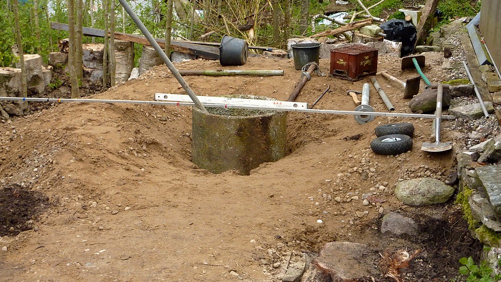
The image shows the results. It is better to have the sides slightly short of 4' rather than too long. This allows whole 8'x4' plywood sheets to fit vertically without gaps.

The aerial image from a stepladder is horribly askew. The foreground alloy bar is actually at right angles to the shed to make the front face square with the house. This also ensures the gap between the shed and the nearest octagon face is even. 

The gap between the buildings is not as much as I hoped but still provides reasonable access between them. There is a path for wheelbarrows on the other side of the shed.

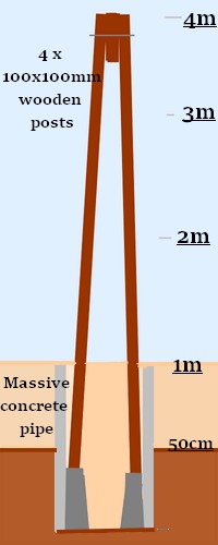
Now the foundation blocks need to be buried. The nearness of the left blocks to the steep bank has already been mentioned. It requires much more sand & gravel to extend the bank outwards. Or  taller posts [stilts] on that side to ensure proper anchorage to more deeply buried anchors. Not ideal, as easy access to the support bracket's height adjustment is lost. It also increases the risk of rot at the base of the timber posts. I may be completely sick of the sight of gravel but there is no option to getting more to do a proper job of the foundations.

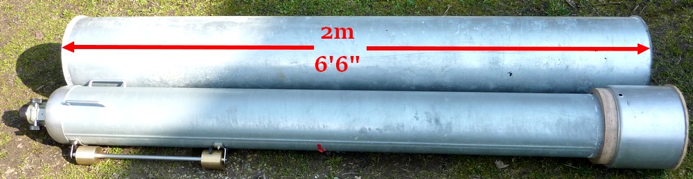
The old satellite dish, on the far right, makes a handy cover to keep clumsy animals from falling into the concrete pier pipe. The water level remains abut two inches below the surface of the small stones I threw in.

Buried two of the concrete footings. Decided not to back fill them yet until I have run strings between them all to ensure alignment. It is very difficult to get the spacing correct using a tape measure and straight edges.

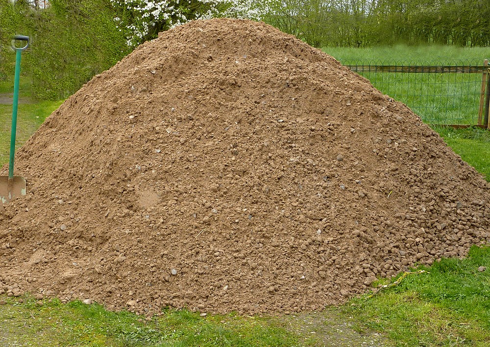
Later I added two trailers full of sand/gravel where the banks are steepest. Need even more! Those drops on the left are black holes! The gravel just disappears beyond the event horizon. It tests the compaction capabilities of the sand and gravel. Raking the gravel over the edge tends to lift just the stones which don't stick together like the more sandy stuff. If it wasn't restrained, by the heavy logs from the birch tree trunks, it would just roll away. It feels as if I need a long bat to compact the slopes but I don't have anything very useful unless I make something. So I am having to stamp on the slope as I rake more gravel over the top. The bank is about a meter high now as the original ground surfaces slopes gently away, from right to left, across the whole site. I'm trying to put a lot more material around the anchors on that side to avoid them breaking out through the top of the bank. The only answer is to keep adding more gravel.


Click on any image for an enlargement.
*

27.4.17

Timbers and anchors.

*
Having completed the gravel movement from the gate to the site it was time to think more seriously about construction. I had decided on an octagonal building which would be supported at the eight 'corners' with 100x100mm [4x4"] posts. These would rest on and be bolted to precast concrete, carport anchors or footings via height adjustable galvanized brackets. No leaning tower of Pisa for me.

The raising of the ground with gravel has reduced the required height of the building to the observatory floor. I had planned on 3m or 10' on stilts but can now aim for 2.5m with a solidly made building. 2.44m is only slightly above the height of a 2.44m [8'] plywood cladding sheet. The observatory floor is intended to extend  beyond the dome walls to become an octagonal veranda. The joists are intended to radiate from an octagonal 'ring' around the isolated pier.

I needed 4m lengths of timber for the overall height, with no waste. As they had only 6m in stock I went with twelve of those. Eight for the octagon uprights and four more for the pier. The off-cuts can be used for cross bracing the framework. Cutting the 22.5° angles should be good fun.

I had help loading the trailer at the timber yard but had to take it all off myself when I arrived back at home. You would not believe the moment arm on an 18' length of timber as it is rotated 90° for stacking. Now do it twelve times.

It was a good job I had warmed up over last few days with all the gravel shifting. Or it would have been quite a struggle handling these heavy items alone. I tried loading three blocks at a time on the sack truck. It was too difficult to tilt it over safely on such uneven ground. They are rather shorter than my original choice but still tapered.  Of course it rained as I was unloading the trailer.

The concrete foundation blocks must weigh well over 30kgs each. I shall weigh them and the timbers later with luggage scales. Just out of  curiosity and being a lifelong pedant. The information might be of use to someone. [The concrete footings weigh 34kg or 75lbs each with adjustable bracketry.] The 6m lengths of 4x4" timber weigh 60lbs each. Or 10lbs per meter.

Cladding of the observatory building is under serious discussion. I used machine grooved plywood cladding for the shed next to the planned observatory. As can be seen just behind the stacks of blocks the plywood surface has weathered to a low impact grey-brown with grainy figuring. These nicely uniform, but varied, plywood sheets would be cheaper and far easier to use than other cladding alternatives with which I am familiar.

It is no coincidence that the sheet width perfectly matches the eight sides of my planned 3m, 10' diameter octagon. The 8'x4' sheets [1220x2440mm] would also have the distinct advantage of acting like a stressed skin to the building once firmly fixed with lots of screws along all the edges. It lasts well out of doors without any treatment and stays flat in my own experience of the shed cladding on 60cm [2'] stud centers. I prefer this cladding option for quite a number of good reasons. The appearance is largely a matter of taste. I like it and it is my building after all.

The adjustable height bracket as supplied. The large, square washer is removed and placed on top of the concrete, anchor block before use. The washer is only placed between the two nuts to stop it from being lost before use. The L-shaped brackets are slotted on their base legs to allow a perfect clamping match with the timber size. The large, flat head of the adjusting screw resists downward pressure from the bottom end of the wooden post. The lower nut, of the two supplied, makes the up and down, level adjustments. While the second nut is used to support and then lock the brackets to the underside of the round screw head.

The alternative cladding would be vertical planks of [say] 1"x 6" [25x150mm.] This is available in opposed planed and sawn surfaces for those who like a choice between simply rustic or downright rustic. I think one-on-two planking would be a bit "heavy" in appearance for a tall, octagonal building. Though thinner wooden strips could be laid over the 1x6s.

Managing the eight 'corners' would be much more difficult with planks. The other most obvious downside is shrinkage, cracking and warpage of natural timber. I would obviously use building paper behind the boards, for waterproofing and draught proofing. There would still be long term upkeep issues if not properly coated and maintained.

A third alternative might be a faux half-timbered look. Plain outdoor plywood with an overlay of boards to suggest oak framing. Half timbered houses are still very commonplace in Denmark. Such a cladding would require painting and regular maintenance and might not even work visually.

The grooved plywood just works for me in an understated sort of way in our natural, rural situation of mixed trees, shrubs and high hedges.

The 'naked' grooved plywood clad shed has taken care of itself for 14 years without the least attention. Though I should really have put downward extended "skirting boards" all around it. Just to ensure no wildlife got in under the wooden floor. We just used heaped gravel chippings around the edges instead and have never noticed any signs of wildlife inside. Any digging would have been fairly obvious at a glance. 


Click on any image for enlargement.
*

26.4.17

Gravel. Day 5 & 6.

*
Wednesday Day 5. The heap outside the gate is shrinking fast. The surface of the gravel on the site is close to optimum. It just needs to be levelled and compacted.

The groundwater in the pier pipe hadn't moved overnight so I began dropping small, clean stones onto the water surface. It took a layer of only a couple of inches for it to remain dry and firm enough for me to stand on it. Though it still has a slight, spongy feel to it as I stamped about to level it.

I am now worried about losing depth of submergence of the base of the four pier timbers in compacted gravel. The concrete footings have considerable height which raises the bottom of the pier timbers considerably. Better, perhaps, to use a cross of heavy timbers. Bolted together with the pier timbers using galvanized [or better] stainless steel bolts. This would act as an anchor and resistive footing close to the bottom of the pipe.

This would immerse the base of the pier timbers to a much greater depth in heavy gravel for increased stability and damping. While simultaneously maximizing the height and weight of gravel above the timber anchor. Which probably amounts to the same thing. The cast concrete anchors would allow a greater splay of the pier timbers over pipe/gravel level. While the cross would force the pier timbers into a tighter bundle by the time they exited the top of the pipe.

Day 6 and all 10 cubic meters, or 20 tons of gravel, has been moved the 40 yards to the observatory site by wheelbarrow.  The next step is to obtain some concrete carport footings and set out the octagonal base around the concrete, pier pipe.

It seems I shall have to order another 2m³ of sand&gravel. The positions of the concrete footings [arrowed] would almost be out in mid air unless the bank is pushed out far more. I could bury the footings much deeper and have longer posts but it seems a weak solution. Particularly as that is the windward side during most storms. I can see the trailer getting considerable exercise but at least the gravel can be shoveled off right on the site. There is the alternative of having a cylindrical observatory building. Which would use more footings on the same radius for greater stability.

 Click on any image for an enlargement.
*

25.4.17

Pier pipe megalith.

*

Tuesday: This morning the excavated hole had 4" of water in the bottom. I still needed to cut away right around the hole to make more room during the drop. The gravel "crater" made it very difficult to balance on the surroundings. An old, plastic beer crate solved that problem. I dropped it in and stood on it as I worked around the hole with a spade. Getting the crate back out of the ooze afterwards took a long lever, a rope and patience!


Finally satisfied with my excavation, I stuck some lengths of pipe against the opposite wall to stop the pipe from digging in as it fell [hopefully] upright. 

By rocking the pipe from side to side as I worked downhill I was able to bring it down to the hole and then rotate it ready for the big drop. My long length of water pipe was then used as a lever inside to lift the pipe quickly upright on the edge of the hole.

The pipe dropped but lodged at a steep angle on one of the upright steel pipes. Excavating around the steel pipe with crowbar solved that problem and I used a Prusik loop and long lever to pull the lodged steel pipe free. 

Now the concrete pipe could stand almost perfectly upright in the bottom of the hole. It looked much too tall at first but a quick check with a long straight edge showed its height was perfect. Now I used my long pole to rock the pipe in the sludge at the bottom of the hole. It took very little effort to get it perfectly upright with the builder's level. 

I expect the 300kg/600lb pipe to sink slightly more due to its sheer weight and soft ground, but I am unlikely to hinder this much by compacting gravel inside or out. The important thing is that the pipe's height, at or below the finished gravel surface, is now ensured.

Barrowing of gravel can now continue once I clear all the junk and tools out of the way. The area to the left has not had much gravel dumped there yet.

A couple of hours of barrowing later the surface of the gravel is rising towards the top of the pier pipe. Each new inch layer of gravel was well stamped down in turn to ensure firm compaction around the pipe. I tried using a sledge hammer as a tamper but it had absolutely no effect.

The view inside the buried pipe shows the high water table after a few hours. Kicking the rim of the heavy pipe had no visible effect on the water surface so it must be well damped.

We have an unused well in the garden whose water surface rises and falls with the seasons. It is far too contaminated with agricultural run-off to be potable.

The presence of water has confirmed the need for concrete [carport] anchors as footings for the four "4x4" pier posts. Any plans to simply "immerse" the posts in gravel, while resting on more gravel would be foolish. As would adding concrete to the base. Cast concrete footings will lift the timber clear of the water while simultaneously providing a larger footprint. A bed of small stones will aid resistance to the footings sinking by firming up the 'ooze' to just above the water surface. The stone I dropped into the water yesterday looks exactly the same today.

Click on any image for an enlargement.
*


21.4.17

Groundwork progress.

*

Clearing access to the site and the platform area itself has been ongoing. I used planks as skis and the chain hoist to drag the massive GEM away from the aggregate delivery route. Chain hoists aren't really intended to be used horizontally because the chain loops tangle so easily without the aid of gravity. The advantage of using the hoist was the slow movement without any rocking. The mounting is very top heavy on its relatively light, slotted angle stand. So I attached cords to the very bottom of the legs for the repeated pulls. First I laid out a lightweight tarpaulin to stop the chains and hoist getting too muddied by the lawn.


The 10m³ sand and gravel mix has arrived. The huge, round pile was 6' tall and two full drives wide. That was before I removed about 30 full wheelbarrows in the first hour. The gravel is remarkably self compacting. Simply walking on the roughly tipped ramp I made was enough to make it firm enough to roll the wheelbarrow down over it.
I'm not sure I can, or should, keep up the barrowing for very much longer today. I just needed to make a path to get past the heap. Fortunately we remembered to put the car outside the heap in case of emergencies. Or rather my wife did.

Next day, the wheel-barrowing of gravel continued. After a couple of hours more work before lunch the area is covered with gravel to a good depth over about a third. We discovered an easier way of filling wheelbarrows by simply leaning them against the heap and raking. My wife did the raking while I trundled back and forth with two wheelbarrows. She filled one while I walked with the other.

Assuming we've spent about four solid hours, so far, the whole job shouldn't take more than 12 hours in total. The exercise is probably doing us good if we don't overdo it. The trick is not to overfill the barrows. So that it never becomes a test of stamina before the barrow can be easily tipped.

Another hour after lunch and the gravel is at least 18" deep over 3/4 of the area to be covered. Say about 9 square meters/yards so far. I am still aiming for a gentle downward slope or ramp until I reach the far end. Just to make the full  barrows roll more easily on their solid, puncture-proof tyres. Not bad work for a couple of 70-year-olds. It all looks an awful mess at the moment but the dry stone retaining wall on the left will eventually disappear. My photography does not capture the scale very well.

Sunday, and two more hours of shoveling and toi-ng and fro-ing with gravel. We are making rapid visual progress but may be underestimating the work left. It will take a lot more gravel to raise the entire surface to match the rest of the parking area. The observatory/platform site seems to shrink as the gravel surface rises. The vast, initial mound of gravel outside the gate is also shrinking rapidly.

The distance to the far end of the site from the pile is about 40 yards. The site is about 4m wide x 5 meters long. My wife keeps suggesting I bury the concrete [pier base] pipe to save extra excavation work through the thickness of gravel later on. With no contractor's machine to worry about now I suppose I could do the digging and burying at any time.The problem is the hard work involved in digging down in the root filled soil beneath the gravel. It is easier to ignore the job and keep on trundling barrows back and forth.


Monday: Another hour and half of gravel trundling between showers in a roaring gale. The gravel level at the far end of the site is getting closer to finished. The middle of the site is being reserved for burial of the big, concrete, pier pipe. A path is being left between the two buildings for maintenance and access. Foreground right is the offending birch stump. I can't start the chainsaw to get rid of it!

Digging the hole for the pipe took three back breaking hours! There were several thick tree roots to chop but no rocks. Coming on top of a couple of hours of gravel moving I am now aching all over. The bottom 20cm / 8" was in heavy, wet clay.

Don't follow my example and dig through a thick layer of sand & gravel first! I was expecting a contractor with a mini-loader to move the sand but it never happened. Had I known beforehand I would have dug the hole in the soil first.

I was just going to try dropping the pipe in the hole when my measuring stick proved to be a bit too tight towards the bottom. It might have gone in by sheer force of weight but it just wasn't worth the risk of it getting stuck half way. I'll have to trim the edges back some more tomorrow. Perhaps make it a little oval to allow it to tip more easily before it becomes upright. I'll have some planks on the opposite side for the pipe's bottom lip to slide down without it digging into the soil and getting stuck at an angle. I have some lengths of heavy pipe to use as levers. The chain hoist would probably cope with the lift but I'm hoping to avoid using it. I'll throw some gravel into the bottom of the hole first for the pipe's lower edge to rest on.

Click on any image for an enlargement.
*

9.4.17

A new tall pier idea.

*
I have a massive concrete pipe in the garden looking for serious purpose into its old age.

100cm tall x 70cm diameter x 60mm thick. [40" x 28" x 2.5"]  It is far too heavy to lift and is a real struggle just to tip it over. [Carefully of course!] It was quite handy for rolling and compacting the gravel for the shed pad some years back. I don't remember clearly how I managed to get it upright afterwards. Probably using levers and increasing heights of support blocks.

I'm thinking the pipe could form the base of a tall, tapered wooden pier. With half of the depth of the pipe buried in the observatory site's aggregate material it could hold four, tall, near vertical, 10cm x 10cm [4"x4"] wooden posts.

Perhaps I should utilize four of the same concrete car port anchors at the bottom inside the pipe? The sturdy timbers would rise to join each other at the top of a tall, narrow pyramid. Where they would be bolted firmly together with horizontal, threaded rods [studs] for a really solid connection. A further length of "4x4" could be fixed between the tops of the four posts to increase the overall dimensions where it meets the mounting base. This could provide a pivot point for the mounting in azimuth via a sturdily dimensioned, vertical stud.

The concrete pipe down at the bottom of the pier would then be stuffed with self compacting sand and gravel for further stability. Being completely protected from the weather the posts would not be subject to much change in moisture levels other than atmospheric variation.

Let's see now:

Pi x D = circumference x thickness = V [volume] of concrete in the pipe's own structure.

V = 100H x 70 x D x th [thickness.] 1cu.m of concrete weighs 2400kg.

V = 100 x 220 x 6cm = 132,000 cc = 132 liters or 2400/0.132 cu.m = 320kg = pipe's own dry weight

Plus the weight of four concrete anchors and the back-fill of sand and gravel of course.  

Internal volume of pipe = Pi x r x r x height. 

3.142 x 35 x 35 x 100 = 380, 000cc or 380 liters or 0.38cu.m. 

Sand and gravel = 1922kg/cu.m. x .38 = an additional 730kg plus or minus the four concrete anchor posts.

320 + 730 <1000kg p="">

If I filled the pipe with concrete: 1cu.m = 2400kg/m^3 x [volume] 0.38 = 900kg.

The difference in weight between concrete and gravel fill is probably not worth the effort of mixing the concrete. Moreover the timbers would shrink over time leaving a gap between the posts and the concrete. The aggregate should not suffer this fate and should remain in intimate contact with the wooden posts. The self-compacting sand should provide heavy damping to avoid vibration excited by the mounting drives or touching the telescope for focusing.

The stiffness of the tapering wooden structure should be an order of magnitude better than a parallel sided steel pipe of the same diameter as the top of the pier. While no lightweight structure, the timber posts should be lighter than  a similar structure made of concrete-filled blocks. The danger with a top heavy structure is its becoming a compound pendulum. With a very low, poorly damped vibration period. Once touched or excited at the top it would go on swaying for long periods. 

To all intents and purposes the pier would act as a solid, tapered wooden pier, very firmly anchored to the ground at the bottom. Its total height would be four meters but one meter would be lost inside the heavy pipe. A further meter would reach above the raised platform but be completely isolated from the platform itself. This should completely avoid footfall vibration of the telescope mounting. This is  thanks to the long path between the platform and the massive concrete pipe. Rather than solid concrete short-circuiting the path, between the pier base and the platform, the sand should help to isolate any vibration.

The hope of such a design is to avoid the likely flexure of a single wooden pole of normally available dimensions. Variations in moisture content might cause warping and affect the polar pointing accuracy of the mounting experienced by a single post. Multiple posts in a tapered design should be far stiffer and each should help to counteract warping in any of the individual posts.

The option exists to sink the concrete pipe to full depth. The top half buried in the sand and gravel and the lower half buried in the site soil. This would provide a [theoretically] better anchorage against rocking but would increase the pier post length [and mounting leverage at the top] by 50cm or about 19". The sand in the pipe could always be removed for dismantling if the pier proves too prone to vibration. Concrete filling would make this utterly impossible. Swings or roundabouts?

The advantage of a fully sunken pipe is that the posts need only be sawn off for the pipe to become a flat surface at ground level. Adding a little extra gravel would make it completely invisible. Without the chore of breaking up, or moving a huge and massive concrete eyesore should the platform site ever need to be used for parking in future.

Digging a hole in the ground soil, to sink the lower half of the pipe, would not be too onerous. The hole would probably aid setting the pipe upright if made large enough to allow the pipe to be tipped, once safely rolled into place.

Even more importantly, the four posts rising cleanly from the ground would not form such a huge obstacle to the use of the space under the platform. This relatively large, 5x4m area, could become a a storage shed or "warm room" for imaging. A large concrete pipe rising 50cm or 19" from the floor would be a considerable obstruction to normal, everyday use. The pier design has very low thermal mass so will not affect the local "seeing." The under-platform construction should also be of wood or boards to avoid solar gain. 

*

Ground-breaking observations.

*

The ground where the raised observatory is to be sited is sloping gently away to the north west. It was once an uncultivated area of bare earth under the shade of two large birches. These have now been felled but with a couple of two feet high stumps still weeping copiously. One of these stumps is directly in the way of site access.

The site is also sunken by about two feet, or about 50cm, below the average ground level. A rough bank of rocks and bricks previously marked the edge of the fall but has been tidied back to firm soil. Calling it a ha-ha would be presumptuous. 

An area of roughly four x four meters x 0.5m deep is 16m^2 ÷ 2 = roughly 8 cubic meters to make up. This assumes that the ground really needs raising, of course. The alternative is to build the whole thing on short stilts. 

The foundations for the entire structure were always intended to be pyramidal concrete carport anchors. They just need a thick layer of some heavy material tipped around them. They seem so neat and functional without all that backbreaking digging compacted soil or concrete mixing. Who wants a massive concrete slab anyway? Concrete mixer lorry access is impossible without a very long pump.

By default, anchors obviously need to be well anchored. You can't just stand them up, like skittles on the ground, and then expect much anchorage to occur.  The usual arrangement is to dig a hole and bury them. The compacted soil around the pyramid defies the larger base the ability to escape at ground level. Thereby adding to the retention abilities of the already heavy [40kg or 85lb] tapered concrete block. The resistance from the surrounding ground also defies the block from moving sideways under load. So far so good.

Importing 8m^3 of sand and gravel would bury the anchors without any hole digging. The problem is sand retention. There is nothing to stop the sand behaving like it normally does. So it would quickly flow away down the garden. No more anchorage!

There are other, more stable materials which could be utilized instead of sand and gravel. Rocks of various sizes are often piled up beside the fields where the farmer has cleared his soil. The problem is handling them. They are individually heavy. Which is good for anchorage. They just don't respond at all well to shovels or rakes. How to get the field stones home in such quantities as to be useful? Loading every stone by hand into a trailer? Not likely.

There are commercially available, stone chippings of various sizes with odd names depending on local traditions. How well they would pack down to retain pyramidal anchors is an unknown. Lorry access to the site is impossible.  I am no longer fit enough to ferry such quantities by wheelbarrow and shovel. Nor is there anywhere to tip a lorry within a hundred yards even if I was still young and able bodied. Or still willing to perform such Herculean tasks as repeatedly wheel-barrowing over many hundreds of yards.

I once cleared an entire 20 acre, unimproved grazing field of surface stones and boulders using only a builder's wheelbarrow. The field stones were all ferried by wheelbarrow to a marshy site beside our home. To form a foundation for the paths of a wildlife garden with ponds and hundreds of trees.

8 cu. meters of sand and gravel weighs about 24 tons. The problem is getting the lorry to the spot where it can tip it or do anything very useful. It's not going to happen even as separate big bags because we have such narrow access to the back garden. 2.3m is the average and minimum width.

I own a 2m x 1.3m x 0.4m trailer but it has obvious limits on maximum load of 325kg. 8 cubic meters is a lot of trailer loads! The sand and gravel weighs 2900 per cu mtr. 1900/325 = 6 trailer loads per cu meter x 8  = 48 trailer loads! Eeek! Then it all has to be spread about.

Which brings me back to digging loads of 2' deep holes and burying the carport anchors but not using sand and gravel . Very hard work based on a recent, very similar project of only one hole to support one steel pole with hand mixed concrete back-fill. I'm feeling exhausted already! 😓

Or, I could have the gravel tipped outside the gate and ferry it the 30+ yards by wheelbarrow to the site. The downside is having to fill every wheelbarrow full, one shovel at a time. The job would be manageable if spread over [say] a week or month to avoid complete exhaustion.

Hire a mini, bucket loader? Say £100 a day for only one day. Job done? This would require careful timing not to have the machine outside the garden on the wrong side of 8cu.meters of mixed sand and gravel. It seems I shall have to hire a local groundwork contractor with a suitable size of mini-loader.

There is another form of  loose sand & gravel. Let's call it self-stabilizing aggregate. It's called stabil[t] grus here in Denmark. Much used for laying drives and leveling parking spaces. 0-32mm is the usual standard and it contains a little clay to obtain its correct level of stability under load. It is variously described as weighing from 1700-1900kg per cu.m.

If properly laid, it has amazing resistance to pressure. Ideally it ought to be plate vibrated in several layers for maximum resistance Since I have no plans for vehicular access in the short term I can safely avoid that step. A top layer of gravel chips can provide a more decorative surface if desired. Though many owners of longer rural drives don't bother with the gravel dressing. Once well established it can cope with heavy lorries rolling over it, without leaving any tracks. Ideal for my purpose where I want to avoid the permanence of concrete. Left suitably smoothed out in a 2' deep layer it should self-compact nicely over time.

I checked a heap of this stuff at a builder's yard and it has a very steep critical angle before it slips or flows. That will help to avoid a tsunami effect of sand flowing slowly away down the gently sloping site. Though I can easily arrange some form of retention until the stuff goes "stiff" at the edges. I have loads of 15" high round  logs sawn from the trunks of the two felled birch trees. They are just sitting around the observatory site and waiting for a better purpose than splitting and burning on a stove. An L-shaped row of logs, one on top of another, should do the trick of retaining the flattened heap.

Over the following week or so I have been steadily clearing and tidying the space in readiness for the self-stabilizing sand and gravel. It has ended up about 5m wide. Times 4 meters out from the dry stone wall enclosing the shed foundation pad of small rocks and gravel. Removing the last of a birch stump was very hard work without a functioning chainsaw. Further research suggests these saws have a nasty habit of being very hard to start unless used daily. Swinging a sledge hammer/log splitting axe at my age is apt to make one breathless. And it did. The heavy, stacked birch logs are now suitably arranged to dictate the boundaries of the sand and gravel when it arrives.

*


5.4.17

How big is yours?

*

My home made, 180mm [7"] f/12 R35 iStar refractor standing 2.3m [7' 6.5"] high on its short, fixed dewshield. For scale I am about 5'10" [1.8m]. Since it overlaps the height of the shed door it has to go in at an angle and is then carefully lifted to stand up between the ceiling joists for a small storage footprint. Not an easy task when it weighs around 50lbs and has a main tube diameter of 20cm or 8". I consider steel toe-capped, industrial safety shoes as essential wear when handling heavy mounting weights and setting up large and heavy telescopes.The grippy, rubber gloves are "handy" too. Providing a greatly increased sense of security compared with bare hands  when manhandling large OTAs. 


Oh, dear. Now my wife wants my observatory to look like this:
A gorgeous, decorative, octagonal, copper-clad, roof tower from a former Carlsberg building in Copenhagen. You'll have to imagine a dome in place of the spherical, wind globe 'basket' on top.

Rescued from demolition and used by a large, architectural salvage, recycling business as a center piece at the entrance to their premises: Genbyg.dk - Denmarks largest online store for used building materials

Genbyg Tårnet på Amager Landevej 185 | Genbyg Bloggen – inspiration, info og tips & tricks

GENBYG.DK - Photos

I had better start building right away! 👷

Bending the framework for my half cylinder "dome" out of aluminium angle is proving more difficult than hoped. The first [of four] arcs is getting close but it is proving difficult to avoid a slight corkscrew effect. I am unsure how important twist will be in the structure. The angle is quite flexible so may be flattened during construction. One gets quite a sense of scale when the arc is hitting the ceiling of a large shed/workshop! One chap on each end, each with a stepladder, was helping to avoid adding twist as the free end towered high above the bending machine. The raw lengths are 6m or about 18'. This length can be trimmed to size eventually. The last foot or so, at each end of the arc, cannot pass properly though the machine due to the spacing of the rollers. I hate to think what this work is going to cost!

Click on any image for an enlargement.
*

4.4.17

High Moon!

*
A clear and bright afternoon promised a clear evening with a High Moon. Well, 45° local altitude, anyway.

I practiced my Scottish caber tossing, while it was still daylight, with the heavy refractor and just managed to get it up into the rings on the big mounting. It really is becoming a hefty lump!

There followed much to-ing and fro-ing as I brought out the AWR drive system electronics and connected it all up. There was a pause for dinner and then it was dark enough to bring out the laptop.

Everything worked as intended except for I-Cap which had followed Stellarium into nano-text territory.  A quick adjustment in the Display menu and stronger reading glasses brought some degree of sanity. Don't ever bother with a UHD screen until they become the norm! Nothing is ready for high resolution screens. Least of all the laptop manufacturers or W10!

The image above was taken with flash at much too great a distance. The AWR drive stuff is on the pier/stand shelf. While a B&D folding workbench holds the laptop. The AWR IH2 handset and a cardboard mouse mat are on top of stacked storage tubs for a rather low working surface. Workable, but far from ideal in the long term. Some protection from dew would be good. Perhaps that's  another reason for building my first observatory at 70 years of age?

My folding wooden chair sits in the background. As is the 12" pipe to which I had fitted a 10" mirror cell only yesterday. It needs an access door but I am loathe to start cutting just in case I think of something else. Like a hinged tailboard?

Finally I was able to settle down to trawling the half moon for interesting features using the slower speeds of the AWR stepper motor drives. These are remarkably positive compared with the awful delays on the synchronous drives on the old Fullerscopes MkIV. Having so many speeds to choose from is luxury indeed. I settled on the "Center" rate, which gave excellent control without excessive speed or unwanted overshoot.There is an even lower "crawler gear" with the "Guide" rate.

At frequent intervals, over a couple of hours, I kept taking taking videos with my Neximage 5 video camera. I managed 28 videos in all. Stuck on the end of a 7" f/12 refractor [84" or 2160cm focal length] the 640x480 Y800 setting can hardly manage more than a large crater or two. See image alongside. I left the 2" dielectric star diagonal in place for easy camera and cable access. Though I do have straight extension tubes somewhere for more serious use, if ever needed.

There were constant thermal issues superimposed on the image on the laptop screen. The house roof was directly below the Moon and had been absorbing sunshine all day long. Whether this was a factor I had no idea but the mounting is far too heavy to move safely. Nor was there really anywhere else in the garden which would actually improve the situation.

I settled on 20 seconds runs or ~500 frames [or less] as I experimented with the camera resolution for a wider view and much larger files. The average file size at 640x480 was 150MB. Sitting out of doors at 38F [and falling] for 2.5 hours is quite a chilly experience. Though my down jacket was fine my legs were getting cold despite the thermal, skiing long johns and thick fleece trousers.  I would have dug out my insulated trousers for future use if it wasn't already late spring here at 55N.

It was too late, last night, to start running my videos through Registax 6. So that will have to wait for today. I'm wondering if I can't transfer them, via Home Group,  to my PC fro more comfortable treatment. Nope! Windows has also dropped free file transfer between computers. So I used a USB sick instead. Only to find the video files were corrupted or would not open. So it was back to the laptop. That Registax was able to extract anything from the violently shaking mush is not far short of a miracle!

I haven't done any imaging for ages so will have to re-learn all the settings of this clever software. I have no idea if I even have anything worth processing. There are far too many options for a beginner, like myself. The image above was one of my efforts after a spin cycle through Registax.The last thing I noticed, as I packed up, was that the polar altitude of the mounting had drooped. The telescope was no longer pointing at the Pole Star. Grrr?  I really must attend to the altitude adjustment. The plate against which it pulls is poorly fixed at the top.

I looked up the details of my refractor fitted with a 7mm webcam sensor. So with a FL of  2160mm my 7" refractor has a magnification of 308x via the Neximage 5. It is no wonder the field of view is so small! The magnification provided is the focal length in millimeters divided by 7[mm]. A binocular objective of only 120mm focal length gives 17x via the Neximage 5 but the distant views still look huge! The downside of these huge magnifications and small field of view is trying to capture whole disks of the Moon or Sun with a long focal length telescope. Not to mention the magnification of any air turbulence. Planets need these large magnifications to provide reasonable image scale. Shorter telescopes would need Barlow lenses to have any impact on tiny, planetary images.

*


1.4.17

Stacked OTAs?

 *
The two OTA's would look remarkably similar to each other if I converted the 12" steel tube to fit the 10" f/8 mirror and flat. 

Both would have much the same length and finish. The refractor has an 8" diameter tube. While the reflector would have a 12" diameter tube. Both would be around 2m or 6'6" long. 

The complete refractor now weighs 45lbs. The empty 12" tube weighs 23.5lbs.
The 10" primary mirror would add about 10lbs. With mirror cell, focuser and secondary adding [say] another 5lbs or thereabouts. The pair would end up not far short of 100lbs once they have been attached to each other and the mounting.

The difference between them is having their objectives at opposite ends. Would the 10lb refractor objective and its cell balance the 10" mirror in its own supporting structure? Where would the balance point lie if both were fixed together? 

It is almost certain that the refractor's 7lbs of balance weights would need to move or be removed. The 10" mirror should carry out their balance duties.

Would both OTA's overload the new "Heavy" mounting? The moment of the two long and heavy OTAs is not insignificant.

Unfortunately I don't have any 12" [30cm] tube rings to test the results of stacking them together.


Click on any image for an enlargement.
*