31.5.17

Building the Octagon Pt.21 Obs. floor joists Pt.2.

*

Yet another trip to the timber merchants for more timber. I needed longer 2x6 material for the obs. floor joists to allow for the veranda. Because of twist and bend in the ordinary framing timber I chose the house building quality instead. I also bought enough 2x4 to add horizontal braces to the walls of the octagon.

My first worry was removing the upper rim joists to make room for the parallel joists. Would the structure move without these braces? It seemed it didn't. So I reattached them as high as possible, tight under the main beam's, timber support brackets. Just to keep everything in reasonable shape.

Now I could lift the new joists up and slide them back across the beams.

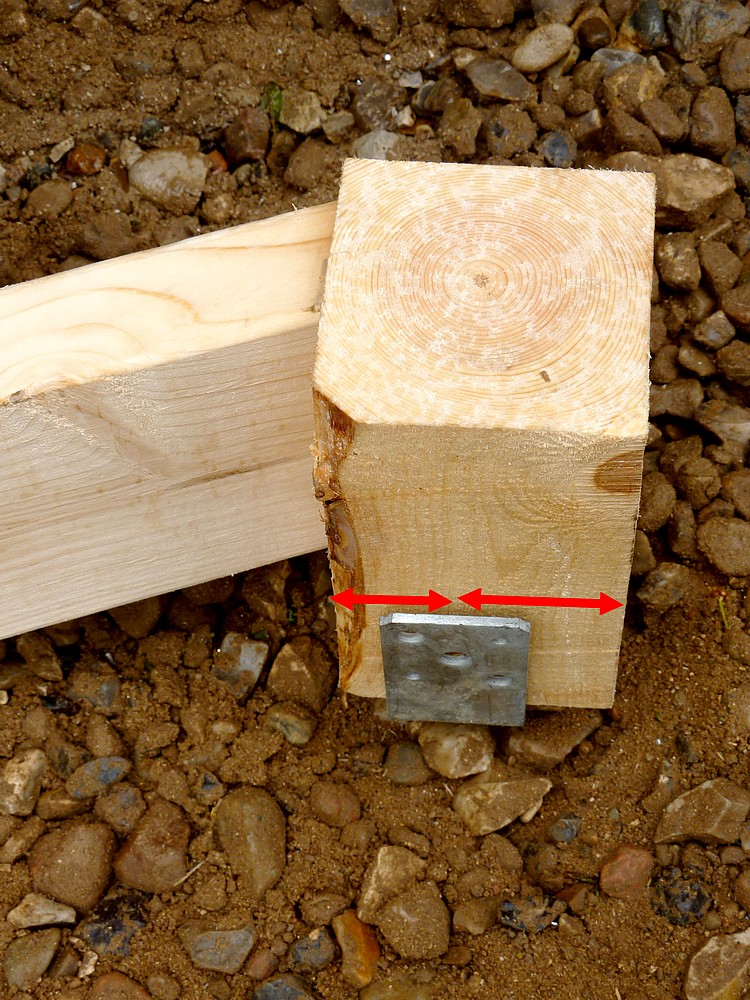
There followed much measuring as I tried to sort out the joist spacing. Having joists tight against the posts changed the spacing. A quick check of the drawing and I saw the problem. The outer posts aren't supposed to have a joist tight against them. Only the inner ones. Not that this is very important because the change is quite small.

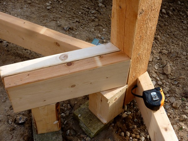
The images show the joists arranged but not yet fixed with nails to the beams. I have donned the white safety helmet after banging my head on the new timbers as I climbed the ladder. I shall leave the beams and joists overlong until everything is fixed before cutting them to length to fit the rim joists.

I'd like to get something to stand on up there so I can fix braces between the tops of the posts. These have to be fixed from outside the structure and there is nowhere useful to rest a ladder yet. So I'll need to stand on the veranda to reach this area. It's not worth the risk to try fixing these braces until I have somewhere safe to work from.

I spent some time wondering about a suitable width for the trapdoor/hole in the floor. It's not just a matter of my squeezing through. So much as the need to pass potentially large or long instruments up through the hole. Rotating the "dome" slit over the trapdoor will provide more pace above if needed for [say] a long refractor. How large an object is likely to need much space?

The length of the trapdoor is very adequate at 117cm between the beams. So only the width becomes important. Should the trapdoor be made wide enough for a much larger [surprise] visitor than myself? In the end I fixed a piece of 2x8 below the joist which sets the width for the pier aperture. I'll think about adding the other side when the need arises and the rest of the joists are fixed. Some shorter joists are needed where they butt against the trapdoor frame. 

Click on any image for an enlargement.
*

30.5.17

Building the Octagon Pt.20 Obs. floor joists and ladders.

*

Today I climbed all over the structure measuring up for the observatory level floor joists. The outside dimension of the octagon across opposing posts is 296cm. Allowing a 60cm width of veranda front and back that makes 4.16 m overall joist length. Joist spacing is 41cm [16"]  and metric 2x6 should be adequate.

I wanted slightly more space around the pier for isolation in case I needed to increase the size of the pier later. The very tall pier is still an unknown quantity and may prove too flexible or too prone to swaying in use. Splaying the four timbers of the tapered pier will require more room for clearance at obs. floor level.

I have also moved the access trapdoor nearer the pier. This provides more horizontal clearance at ground level to reduce the steepness of the stair. The amateur astronomer user is very like to be carrying something whether ascending or descending. The steeper the stair, or ladder, the more difficult the climb. The user is very likely to be tired and/or cold and certainly elderly. Lighting may not be ideal if the user is trying to preserve their dark adaptation.

Anything which make the stair less like a ladder is a very good thing. Proper treads are also very desirable. If a ladder provides access, then a stepladder provides relaxed working platforms at each tread. There is world of difference between a ladder rung and a tread with depth. Forum advisers have suggested a commercial stepladder be modified for the task. While certainly a clever idea this may well set a practical limit on the minimum slope angle of the stairs.

So off I went to check the octagon: As can be seen from the image the ladder is set at exactly 60 degrees. This provides a 50x50cm clear "landing" at ground floor level. The difference in floor height is 245cm.

It should be remembered that the "upstairs" also needs a safe landing space. Climbing onto a flat [floor] surface from a ladder which simply stops [or starts] at that level is very hard work! Usually involving a careful balancing act or crawling away on all flours! Loft ladders should provide an extension of the handrails beyond loft floor level.

I have no need of a retracting ladder and automatic trapdoor but I do need real safety. So a banister rail [or two] is going to be vital to provide a safe continuation of the sloping ladder or stair to allow the climber to balance in that vital moment when they arrive at the obs.floor.  The large "hole" in the floor cannot be left open. A sturdy, hinged trapdoor is vital for safety. So that the trapdoor itself becomes a natural extension of the obs. floor when closed. A shelf near the landing site might be desirable to improve the transition from climbing to arrival at obs. floor level. Care must also be taken to avoid rising directly under the mounting's counterweights!

I have been looking at the ladder manufacturer's offerings which have "proper" treads. They are certainly expensive! The odd thing is that they don't give specifics on lean angle in use. How, on earth, is one supposed to guess this vital information? If the lean angle is wrong then the flat treads will be at the wrong angle too! Many websites use exactly the same image of only one example while a whole range of different sizes is offered. Taller stepladders usually taper. This tapering isn't shown most of the time.

It has just occurred to me that I could use a normal, double, sliding ladder. When arranged properly the pairs of offset rungs are essentially deep treads. The downside is the relatively narrow width of most ladders. Noise in use is also an issue. Wood is quiet but aluminium noisy unless well fixed to kill the natural clang. Clanging an observatory, metal ladder in the middle of the night is certainly not on!

If you haven't discovered the benefits of useful tread depth then you really ought to. One can easily balance without hands on a stepladder because the treads offer excellent and natural feedback through one's soles. On a normal ladder you need knees or hands to maintain balance because your feet rock freely on the narrow rungs.

Interestingly[?] Denmark's ladder manufacture seems never to have caught up with UK ladders. The latter have their slightly triangular rungs "rotated" to provide a flatter, wider and much more comfortable surface for the feet. Danish ladders force the user to rest their feet on the sharp shoulder of the square rung when the ladder is tilted as normal. Historically, Danish manual workers wore wooden soled clogs. So perhaps nobody bothered to update the ladders when construction workers moved on to flexible soled, work boots?

One manufacturer [Alulock] have a deeper tread on a straight, single ladder. They are rather costly, probably because the rungs are a much more expensive profile than a normal ladder rung. These ladders are sold for stores requiring access to high shelves.


Click on any image for an enlargement. 
*

29.5.17

Building the Octagon Pt.20 Outer beams.

*

The floor plan requires a beam to be fixed to each pair of North and South posts and running E to W. These must be long enough to provide support for the cantilevered veranda and parts of the obs. floor.

The image shows all four beams now in place. The far beam is still hanging from cord loops while I pause for lunch.

The plan calls for 2x8 beams [nominal 50x200] and that is what I shall use. Fixing the beams to the posts requires flats to be cut on their outside faces and corners. This will provide a small notch for the beam to rest on and avoid localized pressure from the sharp, vertical edges of the posts. Bolting such a sharp edged joint would simply crush the fibers of the beam locally and provide very little support. 2x4 timber brackets, fixed to the posts, will help to support the outer beams.

After lunch I added the 2x4 brackets and used screws and bolts to fix them to the posts. The image shows only one 1/2" x 7" bolt but I shall use two for each bracket when I have regained my strength tomorrow. I forgot to use the NMN adhesive, too. So they'll have to come off and start again.

I used some 1x4 timber as crossed braces between opposing posts. This had a remarkable effect on the stiffness of the entire structure. Even enough for a fuzzy snap of "our hero" posing on the edge of the top deck to give a sense of scale.

Somehow my wife seems to have found a way of overcoming the image stabilization. Or perhaps she simply wanted to save my blushes? Unaccustomed, as I am, to public appearances. No doubt the NSA is running its facial recognition algorithms as we read this.  If they can sharpen the picture a little they might like to send the improved image back for use on my blog. If it's not too much trouble. 😎


Click on any image for an enlargement.
*

28.5.17

Building the Octagon Pt.19 Fixing the beams.


Sunday morning and showers have arrived with a delightful drop in temperature. They probably won't last long but they will stop progress for the moment. Keen as I am to refit the beams I ought to hold off until the glue has set. Lots more than anticipated squished out of the joints as I cranked on the nuts. It was runnier than  expected and literally fell off the wood as it squeezed out. I made a bit of a mess scraping the excess around the various cracks in the timber. Just using odd off-cuts of wood which were lying about. The dried glue is off-white and has a slightly rubbery consistency. I haven't tried scraping it yet.

Once the rain cleared I started work on the main beams again. Using my laser rangefinder I double checked the distance between the posts at both floor levels. The hanging cords made it incredibly easy to manage the beams independently without danger or repeated heavy lifting.

First I fixed the inner [mitered] beams to the posts with 4 x 4" screws. There followed the fixing of the outer beams, again using 4 x 4" screws at each end. The doubled beams were well clamped together to ensure a close fit. I shall bolt through both beams and the posts as an extra precaution when I obtain more 12mm/ 1/2" galvanized threaded rod [studding or all-thread.]

The poor man's drone, camera-eye view from a ladder up against the gable end, ridge of my shed.  Beams now well fixed with 8 x 4" screws at each end. I have now used exactly 90 x 4" screws.

The improvement in stiffness of the octagon structure was very obvious in line with the beams. Though it made no real difference perpendicular to them. Only finger tip pressure on the N and S posts is required to make the whole structure sway in and out. Pressing in any direction on the posts, now attached to the beams, produces no movement.

I think I may have to run cross beams between the doubled beams. Then carry them through to the upper rim joists. Except, that the present, 2x6 rim joists are "history." They have to go to make room for the obs. floor joists. The parallel floor joists going on top of the beams would probably stiffen things up in that direction [N-S] but working on a flexible structure makes all measurements rather pointless. It is also feels insecure working on such a swaying structure.

For this image I am indebted to members of Cloudy Nights Forums. The author was kind enough to voluntarily provide drawings for the beam structure and overlay of obs. floor joists. Other members provided unique insights and suggestions for improvements as the plan rapidly progressed to completion. With regular interjections on my part to spread my usual confusion. 

Blue shows the support beams and brown the Obs. floor joists and rim joists lying on top. The nearby shed curtails the potential for a veranda right around the building. So the veranda and balustrade will stop on a line just outside of the two nearest posts to the shed.

Without the freely given assistance of these building experts my project would have been much the poorer and certainly flimsier. Their vast experience allowed them to find a safe and workable solution based on my own, existing, half-built,  octagonal structure. I had rather half-baked plans for radial floor joists emanating from a central [floating!] octagonal ring. [Believe it or not!] The present arrangement is vastly superior to any of my my own ideas. I just hope I have the skill and persistence to complete the project to their own very high standards.

It goes without saying that I am extremely grateful for their kind assistance. Anyone attempting to copy the design [without written authorization] should realise that this was a personal response to my own, personal project. The author[s] of the image[s] and any others involved in its conception cannot possibly supervise anything anyone else might do with the drawing[s] or the design.

Your own work is as limited to your own skills [or complete lack of] and any personal understanding, knowledge [or complete lack] of the problems and safety of any structures or building work involved. Don't blame the messenger[s] for your own handicaps and limitations. Build your own design. You copy this one entirely at your own peril! The authors were full of even better ideas but I desperately wanted to avoid demolition of my existing octagonal structure.  So, basically, I wouldn't recommend you even start from here! 😉


Click on any image for an enlargement.
*

25.5.17

Building the Octagon Pt.18 Second doubled beam.

*

After finding some longer clamps I decided to have a practice lifting the second doubled beam into place. The shorter, inner beam was easy enough but lifting the 4.2 meter [14'] uncut beam was much harder work. The beam will not go over the timber bracket until it is almost horizontal. Then it slides easily enough despite its great weight. 

The trick was to lodge the lower corner of the beam safely onto the bracket while I dashed over to the stepladder at the other post. Twice the beam slipped off the far end and see-sawed inexorably down to the ground. I had placed the other end of the beam over the stepladder, hoping to start the final lift as high as I could. Third time lucky and then it seemed to like it up there. I hastily added whatever clamps I could still muster. Then I threw a ratchet strap over both pairs of beams and lashed them together. It has reached 71F today and by now I was bathed in sweat! Am I having fun yet? 😎

The shops are back open today and I need to get some construction adhesive, some 12mm galvanized threaded rod [studding or all thread] and a few more clamps. My small collection of G-cramps [C-clamps] can't cope with paired, 4" posts. I don't have enough bar clamps to be in more than 2 places at the same time.

I even had to resort to the orange strapping to keep the heavy beams safely in place. But these pull the octagon out of shape. Just pushing on any of the support posts makes the octagon flex in and out on either side.

Working alone has its limitations as far as safety is concerned. A suitable clamp can be a lifesaver. But should not be relied on without careful consideration of the consequences of movement or even failure. Just climbing a ladder set up against the structure could distort it enough for a clamp to slip. I have been using the stepladders as much as possible but they aren't very tall and rely on flat ground for stability.

The quality of many, cheaper bar clamps leaves an awful lot to be desired. They are obviously thrown together from the cheapest possible materials without a care for reliability. Even the bars themselves are often bent like bananas from new. Or the vital toothed edges hardly visible at all. Who knows what the strength is of obviously mass-produced materials? Any thought of testing their products to destruction at the factory should be a considered a bad joke. Even the most cursory inspection must have been done in the pitch dark.

My second builder's merchant of the day had Bessey F-clamps "Made in Germany." Expensive, but most obviously better made than the cheaper stock. I can't manage the hand strength required for the pistol grip and trigger style clamps. They leave my hands feeling sprained after lifting all that timber repeatedly over the last week or more. I also bought a cartridge of NoMoreNails and a couple of meters of galvanized 1/2" threaded rod.

I plan to lower the doubled beams off the timber brackets for gluing and bolting the brackets but not take the beams all the way down to the ground again. The weight can easily be held with Prussic loop cords around the upper posts. Or even temporarily tied off to the octagon, rim joists.

I chose to use the 2x6 octagon rim joists to support the beams on rather slack cords. It was important to be able to move the beams freely around so that I could remove the timber brackets without damage. I used a small crowbar to push each beam off its bracket. This went well and without any drama. I then went around removing clamps and brackets. The image shows the pairs of beams hanging from doubled cords with a separate cord for extra insurance. The timber bracket is still in place and held by a G-cramp.

The sheathed cord is nice stuff to work with provided the correct knots are used. For the main suspension cords I used figure-of-eight knots which can always be undone by hand even following heavy loading. It is also a very safe knot against slipping and cannot form a slip knot/noose around a climber's waist, for example.

The brackets will now be drilled 12mm/ 1/2" with the holes arranged on a diagonal to avoid causing splitting. Then the construction adhesive will be used to reinforce the joints with the posts. Followed by threaded rod with heavy, load spreading washers to compress the brackets tightly into the post notches. I shall finish by plating over the brackets/post joints with nail plates. While I may not have much of a shoulder to support the brackets, the glue, bolts and plates should be safe enough working in unison.

The latest image shows the brackets bolted into place. I was even allowed to trim back some of my wife's collection of different oaks. Later, in unpleasantly warm, 75F and full sun, I applied the NoMoreNails to the brackets and re-tightened the studs. NMN needs 24 hours to gain strength so I shan't hurry to replace the beams.

Sunday morning and showers have arrived with a delightful drop in temperature. They probably won't last long but they will stop progress for the moment. Keen as I am to refit the beams I ought to hold off until the glue has set. Lots more than anticipated squished out of the joints as I cranked on the nuts. It was runnier than  expected and literally fell off the wood as it squeezed out. I made a bit of a mess scraping the excess around the various cracks in the timber. Just using odd off-cuts of wood which were lying about. The dried glue is off-white and has a slightly rubbery consistency. I haven't tried scraping it yet.

Once the rain cleared I started work on the main beams again. Using my laser rangefinder I double checked the distance between the posts at both floor levels. The hanging cords made it incredibly easy to manage the beams independently without danger or repeated heavy lifting.

I fixed the inner beams to the posts with 4" screws. The improvement in stiffness of the octagon structure was very obvious in line with the beams. Though it made no real difference perpendicular to them. I think I shall have to run cross beams between the doubled beams. The floor joists going on top would probably stiffen things up in that direction [N-S] but working on a flexible structure makes all measurements pointless. It is also uncomfortable working on a swaying structure. I shall bolt through both beams and the posts as an extra precaution.

Click on any image for an enlargement.
*

Building the Octagon Pt.17 Put a lid on it!

*
It is another warm and breezy day. I have been very lucky with the weather. Hardly needing to cover the huge pile of timber overnight.

I woke early and was muddling over a design for the observatory roof in my head as I waited for a suitable time to get out of bed. 

A double pitched [Mansard] roof is as close as it is possible to get to an arc using only two straight lines. Rotating those lines into an octagon provides a polygon which is close enough to a circle. The result is a simplified hemispherical "dome." One which uses only flat surfaces and straight edges. 

This double pitched roof is not as material efficient as a perfect sphere. It must be slightly taller and of larger radius to provide the same internal clear radius. This step is achieved by choosing the minimum acceptable clear radius [for swinging long telescopes inside] and then simply drawing the two tangents.  

There is even room for a handy joining strut to reinforce the bent joint without obstructing the arc of the internal radius. Note how the upper and lower tangents may be slid around the arc to change the shape provided the edges still meet in the middle.

The next trick is to avoid having heavy timber braces inside.These would greatly reduce the internal swept volume. In other words, the internal radius of minimum arc would shrink considerably. 

So I'm now looking at constructing an octagonal, double-pitched framework from aluminium angle profile. Logic suggests eight, long, isosceles triangles should run from the top down to the edge of the roof. A tall, thin triangle which is bent at half way.

An important pint is that the lower inside edges must clear the building's own octagon. So one octagon rotates relative to the other. The projecting "points" between the two octagons must not interfere with each during roof rotation. This is obviously not as geometrically efficient as two circles rotating around each other.

Consideration of stiffness suggests a top triangle and a lower trapezium. This automatically provides right angle, edge connecting surfaces between the eight upper, triangular panels. The joint between the upper triangles and the lower trapeziums will enjoy a similar connection but would need to be angled. An obtuse angle is required to set the change in slope midway down the roof. 

Critics will point to the slight error in the standard right angle profiles where they meet. This problem could be overcome by a slight bending of the edges of the cladding aluminium. Or a fairly stiff, but compressible, sealing material could provide a wedge between the angle profiles where they meet. A weather strip over the vertical joints is normal. While a slight overhang of the upper triangle cladding, over the lower trapezium, will ensure rain runs off the upper panel and onto the lower one. What could possibly go wrong? 😏

The rotating roof must obviously be furnished with an open slit for the telescope to look through. Is it vital for the telescope to be able to see vertically overhead? [Zenith.] Most amateur astronomers would suggest it is. This would require an open hole at the apex of the roof triangles. Life is suddenly getting much more complicated. A strong, closed ring obviously isn't much use. So it must be an equally strong, open semicircle leading downward into the open slit. The slit is a local break in the strength of the roof. The closed panels are sheathed in aluminium for a stressed skin effect. Fresh air has no value when it comes to strength of an open panel.

What works aesthetically in the way of a shutter, or shutters, on a double pitched octagonal roof? Can one of the octagonal panels be simply hinged aside? That might work with the upper triangle. Opening the entire lower trapezium would be much too wide! Think of the slightest wind dragging on that huge panel! Eek! Most dome, observing slits are parallel-sided regardless of the design of the shutters. Bi-parting shutters probably make most sense with an octagonal roof. What about the join between the upper and lower panels? The edge of the slit is going to need serious reinforcing. Not only to retain the geometric strength of the roof construction but also to support the shutters.

Click on any image for an enlargement.
*


24.5.17

Building the Octagon Pt.16 Raising the first beam.

*

After some effort I managed to hand saw some fairly neat and flat miters at 22.5°. The problem is that what fits perfectly down at the ground is very different 7' in the air. The angles have changed because of the twist in the posts and small angles of post lean are greatly magnified. The orange ratchet straps were used to pull the posts upright. So that my laser rangefinder read the same distance between opposite posts at the ground and upper floor levels. 

This image shows the first inner beam raised as a trial piece to discover any problems. The timber brackets are merely held with old bar clamps. I really ought to get some new and much better ones. Like many of my hand tools, my few remaining clamps were all bought secondhand.

I used ladders to provide the initial beam support while I clamped the brackets to the posts. The lift was not too difficult with just a 3m, 10' length of 2x8 to deal with.

The outer beams will be longer and heavier so I had better get the brackets properly fixed! They will have to support more than double the present weight plus the entire floor system on top of that! The notches are beginning to seem more essential than merely desirable. While construction adhesive will offer a good deal of extra insurance if I can find the right one. Bulldog toothed washers have worked well on all the joints on my shed.

I had a good look at the timber bracket options and returned to 4x4. With a slice off at 22.5° it will not project beyond the exterior octagon line. Every other option involving 2x4, 2x6 and 2x8 would require a hole in the sheathing plywood. Which would be a bad weather magnet unless carefully sealed. The 4x4 timber supports the full width of the doubled beam but not over a very large area.

With a little experimentation and reversal on the saw bed I was able to cut a 40cm or 16" length of timber to the correct angle. The trick was to clamp a scrap length of 2x8 square cut timber on both sides to stop the 4x4 from moving about during the cut. The limitation on cut length was due entirely to the DeWalt's hard, plastic, sawdust collector funnel not  passing over the 4x4 when the miter saw was set to 22.5°. A 45° miter would have been even worse. 

A quick plane over the sawn surface and I had my first, finished timber bracket. Next I need to notch the post to provide some more serious support. It has been emphasized by my forum experts that bolts alone are not enough. I shall use one of my routers with a jig clamped in place on the post. It is quite windy today, so the sawdust from the router will be flying everywhere!

I couldn't use the router jig because of the tie back to the shed. It would have been too much work to remove it. So I used a router freehand with a 1/2", 12mm bit to make a pocket 1/2", 12mm deep. Once full depth was a achieved I chiseled away the uncut rim which was left behind. A final smoothing with a bull-nose plane and the notch was acceptable. The bracket only fills the lower half of the notch. The doubled 2x8s will pass over it and rest on top. The bracket provides two flat, opposed surfaces parallel with each other. So safely avoids problems with clamping oblique surfaces.

I did not dare to greatly reduce the post at midway in case it weakened it. With a low deck it would have been perfectly normal practice to notch the post to the full depth of the doubled beams. With a deck there are no bending loads on the notches.

My two storey building is quite another matter. Wind loads on the top half of the building will try to flex the notched posts. Timber is apt to flex where it is weakest or thinnest. Filling the notch with a glued and bolted lump of solid timber will help to bring back some of the lost strength. Though this assumes the glue is as strong, or stronger than the wood itself.

The last image shows the first, doubled 2x8 beam resting on the oddly-shaped, [4x4] wooden brackets. The inner beam has an acute miter angle on each end. This angle fits against the notch in the upright post. The full length beam then lies alongside and overhangs beyond the octagon to provide a strong support for the planned veranda.

Once the bracket has been glued into the notch and bolted in place the beams can safely carry the floor joists above. The two, doubled beams will be screwed to each other and to the posts. The octagon of upper rim joists [seen just above the beams] will have to be moved to the tops of the posts. This will make room for the parallel floor joists resting on the beams once all flour are raised into place.

The second notch was more quickly cut out by using the router with its adjustable fence. This left a much smaller frame to be finally chiseled away. An alternative would have been to clamp battens beside the notch to set the depth of the router cut via its base plate. The router base needs support or it will go on cutting all the way through whatever it rests on. While I ended up looking like an off-white snowman with my clothes and hair plastered with thick sawdust.

Today I repeated the notching of posts and sawing timber brackets.

Click on any image for an enlargement.
*

23.5.17

Building the Octagon Pt.15. Glued wedge brackets?

*

The CN building experts are suggesting I use construction adhesive to strengthen and stiffen my build. A trial, dry build is recommended before applying the construction adhesive. Once glued, there is no going back to adjust levels.

I can well understand the advantages of gluing the beam support blocks [brackets.] Even with the planned use of 12mm [1/2"] bolts and heavy, load spreading washers, the joints rely only on friction. Glue, these days, is usually stronger than the timber itself. I tried to get bulldog toothed washers while shopping for 7" bolts but none of the outlets had the right size in sufficient numbers.

I plan to wrap 2x6 timber around the posts in an L-shape as beam support brackets. The beams themselves are only 2" wide so increasing the support area only reduces crushing forces. With doubled beams the support area is also doubled provided one isn't mean with the supports.
Bolting the beams through the post will increase support.
Local flattening of the post's sharp corners will increase friction and reduce crushing forces.

A 22.5° mitered block [dotted line] cut from 4x4 might make more sense in place of the 2x6 brackets in the image. Such a wedge would provide far more support area. Without requiring an exceptionally long bolt to hold both beams to the post. Hot galvanized studding [all thread] could also be employed here instead of bolts.

I am not sure how long a wedge can be cut at 22.5° on my compound miter saw. The figure of 22.5° is actually 67.5° but that is thwe marking on the miter saw. Perhaps a suitable wedge can be assembled and glued for this purpose from two or more pieces of 2x8 timber? If the laminations were laid flat on the 22.5° angle of the post there would be no tendency for the laminations to shear along the glue line. Any limitations of the saw to cut 4x4 material on the diagonal could then be overcome.

Only local counter-boring or pocketing to provide a flat surface for the bolt heads, washers and nuts is required in the posts. It is not good good workmanship to use a bolt on a sloping surface. It will try to apply a lateral force to the materials being joined. Not to mention the local bending forces on the bolt. The bolt head and nut will be asymmetrically supported and unable to provide the pressure and resistance demanded. With consequent loosening or damage to the materials being joined over time.

The next image shows what happens when real timbers are mocked up to show the connection with reality. The beam at the top of the image passes right over the bracket and rests upon it. That's fine. The second beam is a problem. I cannot cut a true 22.5% to fit inside the small green angle since the saw can only leans over by about 45° maximum.

I can cut a 25° [true 65°] to butt against the upright support post. Though that means there is a gap to the second beam. So the two beams cannot be fixed directly to each other. I shall have to add a series of solid timber spacers along their length. This seems be acceptable practice when building support beams for decking. Provided, of course, the beams don't rely entirely on coach bolts for post support. The post could be notched [undesirable in my build as it would weaken the posts] or support brackets provided for both beams.

Each beam to post connection would have a separate "packing wedge" cut at 22.5° on the miter saw to fill the empty angle between the post and the beam. This would spread the compression load between the post and beam without needing to cut flats on the posts.  Long bolts [or studding] would pass right through the doubled beam and the post. With a small 22.5° wedge shaped packing piece on the opposite side of the post to provide a perpendicular bolting surface.

Then I thought I could use the inner beam as the packing piece. It just meant I had to saw the acute miters by hand saw rather than using the miter saw. Which couldn't even be lifted high enough for the saw blade to pass over the top of the 2x8 set on edge! I removed the large stop screw to allow a little more elevation but then it was difficult to balance the 2x8 on edge.

I then fitted the tall fences and stuffed a wedge of timber behind the 2x8 but it didn't really help much. The image shows the results of my labours with both beams clamped against the post. I only need to cut four of these acute miters so I shan't get much practice at miter sawing by hand.

It was suggested that I could raise the far end of the plank and then saw with the miter saw set right over at 45°. Sadly, that didn't work because the DeWalt's guard linkage got in the way.  The last image shows how deep the blade would go before it would go no further. I think I may be marginally better at sawing by hand. And was, after the first two trials.

I am still being advised to notch the posts for better location and support of the beams. I still have the crude router jig I made earlier.


Click on any image for an enlargement.
*


21.5.17

Building the Octagon Pt.14 A new and superior floor design!

 *

My expert advisors on the CN forum have been teasing me with regular design updates to my original octagonal building. They wanted to overbuild the thing compared with the original spec. I'm trying to find an alternative way around this if only to save myself having to lift long and massive timbers while working alone.

I suppose I could take a week's rest and then start building again when the design is fully hammered out. I am joking, of course, and absolutely no criticism is intended. I am very grateful that anyone who would try to help me put together a strong and safe building. I am, after all, enjoying the voluntary efforts of a personal design team built on their own, long experience in the field. Bouncing ideas off one another has resulted in  a better design from my own point of view.

To which I can now cheerfully add a new obs. floor design and support structure from my ever-willing advisers. I get to keep my present octagon structure and the additional 2"x8" support beams are still manageable in size and length. The image shows the underfloor beam structure. To which I am indebted to Midnight Dan a member of Cloudy Nights forums.

By using doubled beams, well fixed to one another, I don't have to lift great weights of 4" thick timber in one go. These beams can also be lifted onto solid timber brackets already bolted firmly in place on the support posts. So no more silliness, trying to fix a heavy piece of timber, while simultaneously holding it up at arm's length!

I knew my shed was rather close to the octagon but the new, extended beam design would interfere with the pitched roof. Easily fixed by curtailing the veranda flooring and supports on a line at the outside of the nearest posts to the shed. The veranda will also stop at the outer post line with the balustrade closing off the extended, front and back "corners." A 2"x8" beam will be supported on timber brackets to carry the overhanging veranda on that side.

The image shows how an extended 8" deep beam would interfere with the shed roof. The thin plank laid on top is just to provide a line of sight for maximum clearance at the top of any projecting beam. Anything lower, than this, soon collides with the roof. Better, I think, to stop the veranda at a beam attached solidly to the posts and running parallel with the shed.

I can start by fixing the 2x8s which butt against the upright posts with 22.5° bevels. This will greatly increase the stiffness of the octagon ready for the next step. Longer 2x8s need to be fixed beside the first beams but passing right beside the support posts to carry the cantilevered veranda. Which needs to be no more than 2' wide. [60cm]

This means I shall have to remove at least some of the existing, upper, 2x6 rim joists. Probably to replace them with 2x8s  to butt against the new beams with 22.5° bevels. First, the posts will need to be fixed firmly together with cross members to avoid the octagon becoming unstable again.

The long 2x8s will need to reach their raised position as easily as possible. So great care is needed not to obstruct a straight, clear lift. Temporarily tying the tops of the upright posts together with timber might best achieve this. I could use the existing 2x6s which are already cut to length and beveled for this. Or, I could keep the 2x6 rim joists in their present positions but shorten them with new bevels. The 2x8 cross beams carry all the weight into the support posts via solid timber brackets. So the 2x6 rim joists are adequate to their task if they are retained.

I could lower the crossbeams to bring the observatory floor to its original height. My own plan was to add the floor joists between the rim joists. Not to add a whole new layer of joists on top. Which would obviously raise the finished floor height by the height of the floor joists. Presumably 15cm or 6" with normal 16" joist spacing.

I need to make a decision about this depending on downstairs ceiling height and the loss of wall height upstairs in the observatory. None of this is truly critical to function but it is worth serious consideration before I start adding the heavy beams. My initial decisions on obs. floor height were a desire for a clear view down to the horizon over the shed's ridge. I have no need of any more in the way of extra height of the obs. floor.

The downstairs floor is now about 8" over average ground level. The underside of the present obs. floor rim joists is 2.32 meters above the ground floor. I think I can afford to lose some height to bring the ceiling height downstairs to 2.1m or about 6'7".

Which leaves me with the decidedly, non-trivial option of adding all of the cross beams without having to remove the present, upper rim joists. I can lift the beams onto their brackets so that they just clear the undersides of the rim joists. The octagon of 2x8 rim joists can then be fixed in place. Once the beams and heavier rim joists are all safely in place the present 2x6 rim joists can be removed. So that the parallel floor joists can go on top.

Just having a solid platform to observe from would be a huge improvement on standing at the bottom of the present, green "well." With the only views of the Moon and planets visible from upstairs windows at bedtime.

Click on any image for an enlargement.
*

20.5.17

Building the Octagon Pt.13. Beams, rim joists and water levels.

*
I think discussion on the CN Observatories forum is leading towards a design consensus. The upper 2x6 rim joists will be doubled to 4 x 6 and screwed together along their length. [90x145] The posts will be bracketed each side with 2x4s to better support these doubled joists. Each completed joint will be plated over inside and out to stop the main support posts from pulling apart under load. The nailing plates main purpose is to control tension loads between timbers. Not to provide resistance to compression, twisting or shear.

I am trying to arrive at an attractive combination of 4"x4" and 2 x 2"x4"s timber brackets. Hopefully one which won't look like an afterthought once attached in a "clump." I am torn between mitering the bottoms of the brackets or making them curved on the bandsaw. The squared off bottom of the 4x4 bracket looks decidedly "amateur" and unfinished to my eyes.

I can see the need for some 45° braces but don't want to start cutting joints. These might actually weaken the structural components locally if it involved removing material to make mortises and tenons.

I bought some clear 1/2" hose to make a water level. This required that I raise my "reference" post slightly to allow the other post's ground clamps to be above minimum height. I was using rather a long length of hose to start with and getting some erratic levels. So I changed to the shorter "half" instead and noticed a single, large bubble. It took some shifting but eventually the bubble rose to the surface of one pipe and vanished. I could then work my way around all the posts resetting their heights via the footing's screws jacks to match the "reference."

An opaque garden hose, with clear end pipes, which is sometimes recommended, would be very difficult to check for bubbles. Garden hose is also rather prone to flattening at bends unless considerably pressurized. Which is why I chose to use thick wall, clear plastic hose instead.

All large bubbles must be eradicated for the level to work properly. The diameter and length of the tube has no bearing on accuracy but the weight increases very rapidly with larger diameter hose. [Pi x r^2 x L] It is best to arrange a length where the middle can rest comfortably on the ground or scaffolding to take up most of the weight. Particularly where the open ends are raised considerably above ground level. A plug in the open end[s] will stop the water shooting out if one end is lowered accidentally. But MUST be removed again for the level to work. Both ends must be maintained at a level close to each other and the sometimes wild "see saw" in levels allowed to subside before the level is "read."

The image shows my method of attaching each end of the hose to the upper rim joists. This is my "reference" end with an arrow showing the meniscus. The level of water in the tube has actually dropped a little since I left it in place an hour before the photograph was taken. This may be just the hundreds of tiny bubbles 'evaporating' over time. The level is extremely sensitive to water being added to top up to a marked line. I simply stuffed a small funnel in the end of the hose while both were elevated and added a little water at a time until the hose was just, full enough. The water [hose] level is a very old device and extremely accurate. Some users like to add some food colouring to the filling water to make the levels more obvious. I had little or no problem seeing the meniscus from across the 3m octagon in bright sunshine. 

My expert advisors on the CN forum keep changing the rules on my octagon building. They want to overbuild the thing compared with the original spec. I'm trying to find an alternative way around this if only to save effort lifting massive timbers while working alone. I suppose I could take a week's rest and then start building again when the design is fully hammered out. I am joking of course and no criticism is intended. I am very grateful that anyone who would try to help me put together a strong and safe building based on their own, long experience.

Click on any image for an enlargement.
*

19.5.17

Building the Octagon Pt.12 Adding load bearing beams.

*

My CN advisors are suggesting I attach 4x4 timber brackets to the upright posts to support the doubled 2x8s beams. The upper floor joists would be laid over these beams from the pier clearance hole right out to the veranda perimeter. The existing, upper perimeter joists will be doubled for greater strength. The image shows a beam mock-up using 2x6s. The angles are the same as the outside bevels at 22.5°.

I collected the four lengths of 2x8 beam timber and a load of joist hangers. They had  special hanger screws which I prefer to short, fat nails. Constant hammering draws attention and gets on people's nerves. Rechargeable drills used as Torx screwdrivers are almost silent except for the ratchet clutches. I shall probably need more 2x6 joists material but will see how it goes. The ground floor will need lots more. So I might as well collect a whole load while I'm at the timber merchants.

I was just working my way around, checking levels on the upper joists, when the heat got to me. I started feeling dizzy and had to go indoors to cool off. It is "only" 70F but the sun feels very hot. The baseball cap didn't help and only made me feel even hotter.

The level of one rim joist was completely off so I had to lower it. The "entrance lintel" joist was slightly too long which was making the left post lean. So I've fixed that too. I could see there were alignment problems when I sighted past the posts. They will have to be corrected before I start strengthening the structure with hefty beams.

The image shows a trial bracket of 100x100mm [4"x4"] timber clamped to bring the 45x195mm [2"x8"] beams to the same level [on top] as the perimeter joists. These beams will take much of the load of the floor joists above so need to be well supported. The beams will also add considerable stiffness to the octagon by preventing it from becoming misshapen.

I might miter the bottoms of the 40cm timber brackets to make them look less "obvious." Then I shall bolt them to the upright posts with long coach bolts and probably star washers. These bite into the adjoining timber surfaces to provide a firmer hold against relative movement. I used these washers extensively on all the joint bolts of my shed framing.

Here a batten has been laid on top of the brackets to check their levels across the width of the octagon. Where a flexible length of timber is used for lightness the level should be placed in the center of the material. If it is placed off-center then the level is very probably sitting on an incline and will give a false reading. Exactly the same occurs with a string/line supported bubble level if placed off center between support points. A stiffer length of timber should not suffer the same curve from sagging as a result of gravity if placed on edge. The downside is that it is much heavier to handle repeatedly compared with a much lighter length of batten. Particularly when one is dealing with a length of over 3m or 10'. Leaving a heavy length of timber resting high up has serious safety issues.

Click on any image for an enlargement. 
*

18.5.17

Building the Octagon Pt.11 Observatory floor.

*

A member of the CN forum has kindly suggested a really solid floor plan and even provided a drawing. It is far better than anything I might have come up with.  My solutions would have involved lots of oddly angled joints with radial joists. His plan uses parallel and doubled 2"x 8"s across the major diameter of the octagon to act as main support beams. The rest of the joists are 2" x 6" and all parallel, but at right angles to the two main beams using short, stiff spans. Now I shall have to obtain more timber and get building.

I intend to leave the walls and ground floor open for the moment to provide firm footing for ladders and scaffolding. If I built the ground floor first it would be exposed to the weather and physical damage for quite some time. It would also require quite a large step up from the surrounding area. I'm not sure it would help improve access for working on the raised obs. floor.

The image shows how the jointed builder's stepladders provide a perfect trestle height for fixing the upper floor joists in place. They just need some suitable planks [or 3/4" plywood?] to walk on and local lashing to the framework for greater stability. With the octagon walls open I can easily arrange the trestles inside and outside the framework. The extended ground braces add remarkable stability compared with ordinary ladders.

These mini-scaffolding/stepladders are probably intended for working from firm, flat floors. Though the large rubber feet don't sink far into the gravel. I sawed out some trestle planks from 20mm Baltic multiply. With all the ladder rungs supporting the boards along their entire length there is no bending moment to worry about.


Click on any image for an enlargement. 
*

17.5.17

Building the Octagon Pt.10 And then there were eight!

*
The last post was more difficult to raise than the previous ones due to a lack of support. Four perimeter joists had to be added. I cheated and clamped some off-cuts to the uprights to give the upper joists something to rest on while I drove the screws home. A try square had given me a scribed line right around each post to ensure no errors crept in.

Checking each joist with the 4' builder's level proved my work wasn't far out. This was confirmed by laying a 2"x 4" across the octagon and checking the levels across the center.

The posts can withstand a good push around the circumference but they are not nearly so stiff radially. This is to be expected before the upper frame is stiffened with joists across the center. Though the Octagon is quite happy supporting ladders against the upper joist ring. The slight floppiness is visible in the comparison between each post's uprightness in the attached images. 

The post spacing across the center was acceptable when checked with a telescopic pole. Which was a bit of a surprise considering my lack of marking out. I do not recommend you copy my slapdash example if you want real accuracy.

The second image shows the view from the upstairs window. The folding beech chair is for taking a rest when I get too hot in the 68F, 78% humidity. I have cleared all the ladders out of the way to celebrate the basic framework's completion. It feels quite roomy inside the building. No doubt that will change when the sides are covered. The pier, telescopes and mounting will all eat up space.

I used a long rope to try and pull back the oak saplings which are crowding the far side of the framework. This did not go well. They are far too stiff to respond to a puny, human pull. I have no problem at all with the flowering shrubs in the left foreground. They will soften the appearance of the building and provide free afternoon shade.


Click on any image for an enlargement.
*

15.5.17

Building the Octagon Pt.9 And then there were seven.

*
I managed to raise the 7th post and brace it before I was called in for a shower before dinner.

This is the view from my dormer window where I sit at my computer. It looks as if the top of the Octagon is level with the bottom of my window frame. Pure coincidence as it was not deliberate.

The heavy duty mounting sits under a tarpaulin in the foreground. The pink mast is from a windsurfer's, flea market, clear-out and supports my wireless anemometer. Though it didn't get much exercise today as it was warm and still. A little too warm for my tastes!

I discovered I could brace the previously fixed post with a 2x6 while I rested a ladder on the outside of the octagon.This allowed me to reach the upper cross brace/joist for 4" screw driving with the rechargeable drill. Then I had to dangle from the stepladder to reach the next post.

Today is cooler and breezy with all-day rain, by the look of it. Thank goodness I can take a rest day! Though it might stop raining just long enough to get the last post in. 😉 It didn't. So I couldn't.

One more post and four perimeter joists and the circle will be complete. Then what? First I had better get all the posts braced perfectly upright. I'll have to see whether a full octagon gains some natural resistance to flexure. I had plans for X-frame braces in the lower sections but wonder whether I couldn't achieve more early stability further up in the structure. Horizontal 2"x 4"cross braces might ensure a stiffer framework since they work radially where they enjoy far more "leverage." There is no point in trying to brace the lower sides if the framework is not perfectly true.

There is another Catch 22: I intend to build a sturdy octagon from 2"x 6" timber at the center of the floor structure at observatory floor level. Joists will connect this frame to the perimeter octagon. The problem is not knowing how small I can make the inner octagon and still clear the massive, tapering 4 x 4"x 4" wooden pier rising through the middle of the floor. Isolation of the pier from the floor is vital but I don't want to have to "childproof" a large gap between them.

Then there is the matter of supporting this inner octagon. Having the pier in place would really help to support it to allow work to proceed with the obs. floor joists. The pier timbers are bolted to concrete anchors at below ground floor level. So could be removed if they become a serious hindrance to building work.

That would also allow the final height of the pier to be delayed until the obs. floor is complete. I really wanted to use the existing slotted angle pier. Just to confirm the required height while resting on the finished obs. floor.    

Click on any image for an enlargement.

*

Building the Octagon Pt.8 Adding posts, joists and braces.

*
Monday 15th May. I worked into the evening yesterday putting up extra safety props and adjusting the ladders and uprightness of the first two posts. Then there was the tidying up of all the tools and timber. There was light overnight rain but I had lightweight tarpaulins over the timber.

I now have to move the tall stepladder to provide support for the next post. This is easier and a safer support than trying to use props as the heavy post goes up. The props come later when I have the post nicely upright and the joists/braces fixed.

The image shows the third post upright and safely lashed to the ladder which has been moved. Getting the ladder in the right place is the most difficult part of the operation due to the lack of space.

Two horizontal  2"x 4" braces back to the shed's rafters have also been added, via nailing plates, to anchor the two buildings together.  The first two posts are now rock solid.

I am now sawing beveled joists to length. This is to save having to stop and make them as required. Fiddling with the DeWalt material stops is still irritatingly sloppy. At least I have found a way to support long work using a stepladder. Now I can handle long timbers in the workshop. Without having to carry the heavy, compound miter saw outdoors every time I need it.

BTW: The extension cables to the site have been wrapped in split garden hose and lifted safely out of the way on a suspension cord.  I thought this more sensible than leaving them trailing on the ground to be repeatedly run over by heavy wheelbarrows full of sand&gravel.

Now I have five posts upright but it is so warm working in the bright sunshine at 66F that I'm taking a break. Moving the ladders around the site between all the braces is a bit of a struggle. Once the posts are upright and tied to the ladders it is straightforwards enough adding the perimeter joists.

Back to work and then there were six. I left the ground level joist out at the entrance to the site to avoid tripping. There is also more gravel to be barrowed in to the left to improve the banks. The posts don't all look perfectly upright because I was removing temporary braces to be able to move the ladders around. So the posts can still lean inwards slightly unless supported by ground braces. I'm hoping the ring will become more self-supporting once closed with all eight posts and upper joists in place.

Horizontal braces and joists across the center will help to avoid the present clutter of the diagonal ground braces. Access to the outside of the octagon is required to allow me to drive home the 4" screws of the perimeter joists. I can't very well lean a ladder up against the same post which is actually being braced. Until now I have been working from the freestanding stepladder while it is simultaneously holding up the posts. With lots of checking for uprightness and leveling of the joists with the builder's level.

Rain is forecast from about midnight and for all of tomorrow. I had better start tidying up earlier than last night. There is no room for the big step ladders on the left until the bank is slightly widened. So I am unlikely to be able to raise and brace the last two posts tonight.


Click on any image for an enlargement.
*

14.5.17

Building the Octagon Pt.7 First two posts.

*
Various contacts have kindly tried to warn me against making dangerous lifts. So I was looking for a simple way to avoid lifting the frame for a whole side of the octagon. That would not only be 4m high but 1.2m wide with three sturdy 2"x 6" cross braces/joists. The 4m [12'] lengths of 4"x 4" are pretty weighty! Doubling them up simply doubles the weight of course. Then it has to be lifted as a unit using props. I have decided it is best not to do it that way.

So it was back to using a pair of my folding stepladders all straightened out. Using suitable side braces they are quite capable of considerable stability thanks to the extended aluminium crossbars at top and bottom. They are lashed together at the top and then used as double height stepladders in their own right.  Reaching easily to 3m [10'] even with very gentle slopes. The bases dig into the soft sand&gravel

I have used this arrangement for all kinds of heavy lifting with a chain hoist hanging from the tops of the ladders. I added a single 2"x 6" ground brace for unquestioned stability and quickly raised the first two posts.

The vertical posts were each roped to the ladders at a suitable height to ensure they remained safely upright. The bottoms of the posts were set in the footing brackets and cycling toe straps clamped them in place. I then adjusted the ropes and ladder to bring the posts perfectly upright using a 4' builder's level.

The plan is to chop out the sockets for the joints before each of the posts is erected. The two lower braces will only be added once each pair is safely raised and secured with lashings to the ladders. The tops of the posts will then be securely braced with 4.5m long 1"x 4"s and cord while I move the pairs of ladders onto the next post. This way there are no tall unsupported frames swaying in the breeze. I can also work quite comfortably completely unaided.

The next image shows the two lower joists in place though rather hidden by the stepladders. Instead of cutting joist sockets with the router I have decided to use large nailing plates over the pairs of 4" screws.

The final ring of cross braces at the tops of the posts can be added once the ring of eight posts is completed. Horizontal cross joists and braces will be added for extra stability before I ascend to the tops with a heavy 2"x 6" brace and rechargeable drill between my teeth.

Click on any image for an enlargement.
*

13.5.17

Building trhe Octagon Pt.6 Whoops!

*
I decided to have a go at drawing the rough idea in SketchUp. Not without some difficulty, I might add. I find the learning curve too steep despite all the YT Beginner's videos I have watched. Like most computer programs they rely on memory and practice. In the absence of either they are as opaque as mud. Enough of the justification for my failure to become proficient:
 
This is a rough sketch of the planned building. Seeing it to scale, like this, has me disliking the arched dome. It might have worked on a squat, square building but the arched design on top jars my senses.

The corners of the 'dome' overhang the octagon and may even leave it bare in places as it rotates unless further oversized.

I suppose the ends of the barrel could be leaned inwards. Lots of image searches around octagon + buildings + sheds + gazebos + barns + domes + observatories and I am still undecided. To make matters worse the observatory will be visible from afar through the gap between the house and the hedge . So doesn't want to be too "obvious."

Click on any image for an enlargement.
*

12.5.17

Building the Octagon Pt.5 Support.

*

The experts on the CN forums have advised me to improve the location and support of my braces/joists. To that end I have routed a test pocket in the upright stump for a perimeter brace/joist. Satisfied that it would be a useful modification I threw together a crude router jig to achieve some degree of automation and a [far] greater degree of accuracy. 

The braces/joists would be supported by the lower shoulder rather than simply relying on two 4" screws. This raises some issues since I really wanted to keep the lower floor as near as possible to ground level. Cutting a pockets sets a lower limit unless I step the bevel on the joists and make a shorter socket. This would leave some meat on the lower end of the upright posts to support the joists. The higher joists need no such special treatment.

Being able to wheel something straight into a building has certain advantages depending on the surfaces. Deep gravel is a hopeless surface for heavy wheeled objects. A raised floor also risks the problem of wildlife moving in unless well sealed on the perimeter. I planned to add skirting boards which would be lost in the depth of gravel chipping as a first barrier. The self-compacting sand&gravel collects on the soles of footwear and leaves a brown trail across the grass. Hardly very practical!  Aluminium flashing also buried in the gravel would provide an anti-digging barrier while rejecting rain and moisture. Paving slabs are an option but complicated by the shape of the building.

This simple router jig would be slid along the 4"x 4" posts. Then clamped at the next pocket to be cut so that the router can do its thing. With 48 sockets to make I could see serious problems arising if the work was dragged out for too long. Using a  jig was suggested on the CN forum. I initially had doubts because of the weird angles involved but my misgivings proved to be unnecessary. The time saving from using a jig makes the large number of joints a practical proposition.

Involuntarily listening to a neighbour's router is no more fun than listening to their chainsaws. Though revenge is indeed a fine thing! There are others, even closer to home, just looking for an excuse to criticize the serious lack of progress. Withdrawal of goodwill is not something lightly to be countenanced! 😨

Friday: Bank holiday. I trimmed the router's add-on, Tufnol base plate to make it symmetrical. I could then reclaim the missing batten by closing up the width of the jig. I also added a stop batten to act as a fence at the front. Further fine adjustment brought the routed socket to a tight fit on the 45x145mm joists. Cutting an accurate pocket is now very much simpler.

The Head Gardener is now suggesting the observatory building be raised on "stilts." This, she claims, will help to avoid vermin living underneath and damp getting into the lower structure. It will also make the ground floor even higher requiring at least one step and probably two. My own feeling is that it will make the building seem insubstantial instead of a permanent structure. The nearby shed hasn't show sings of infestation or damp. Now I cannot progress with making ground floor joist sockets in the posts until the exact height is known. 


Click on any image for an enlargement.

*

10.5.17

Building the Octagon Pt.4 Brace yourselves.


*

Here, a trial length of mitered 2"x6" [actually 45x145mm] was screwed to a couple of off-cuts of the 4"x4 posts." This gave me a useful gauge to try around the entire octagon of footings.

Getting the sharp edge of the miters flush with the outer corners of the 4"x4" required some care. The cladding will be screwed to both the posts and the cross braces so, ideally, both need to be flush with each other at the outer edges.

The 100mm [4"] chipboard screws need a lot of torque unless the holes are pre-drilled 4mm. The maximum torque setting of 15 was not quite enough on my DeWalt rechargeable drill to sink the screws fully home in either gear. The only remaining setting is for drilling and this has no slipping clutch. So the drill handle turns viciously when the screw jams tight.

I think I will invest in a self-countersinking drill holder to match the needs of these NKT screws. This will save a lot of time trying to bring the boards exactly to the outer corner of the 4"x4"s. I'll just need to run the drill in to ensure exact placement of the 2x6s. Failing that I can pre-drill 4mm through the 2x6s to enter the the 4x4 for board location prior to driving the screws.


I also discovered that rotating the footing brackets by 90° allowed the 2x6s to sink much lower without obstructing the brackets. It also allowed a much greater degree of leeway regarding the separation of the footings.[Arrowed in the image above] Originally, I was placing the brackets on either side. Rather than inside and outside the octagon's perimeter. The new position allows me to mass produce the cross braces without measuring the exact distance between each footing. The distances between centers are within an inch of each other anyway.

Tradesmen use compound miter saws on building sites every day. They would probably see my project as rather small beer. I should have gained some valuable practice with the saw by the time I have finished the building.

I still need to overcome the floppiness of the totally crap DeWalt, adjustable material stops. Folding, adjustable height legs, to prop up the equally floppy, extending support arms is high on my list of things to do. For short, lightweight picture frame moldings these saw stands are okay. Anything with any length or weight is hopeless unless supported at the correct height.

Why DeWalt omitted drop-down, adjustable legs as standard for their tool support stands is anybody's guess. Without a prop the extended arms and length stops are all but worthless! I have just found a YT review showing optional support legs but at a truly ridiculous price. A length of 1"x2" should do. Then all I need is to arrange a stop which actually works! Shame on DeWalt for penny pinching and then profiteering on accessories.


Click on any image for an enlargement.

*

Building the Octagon Pt.3 Bad weather stopped play.

 *

Wednesday. [Yesterday's tomorrow.]  The forecast is for rain all day and the huge stack of timber is under lightweight tarpaulins. I want to make some 2"x6" cross braces to check the angles are true. I may use short lengths of scrap 4"x4" to make a scale model for the main posts. This will avoid handling and cutting very large and heavy objects outdoors in poor weather.

I just need to arrange enough space to support a 3.6m length of 2"x6" and still be able to use the saw in the workshop out of the rain. The height of the cutting table on the DeWalt miter saw is well above that of my B&D folding workbenches. I may need support packing to keep the timber in good contact with the saw table. 2"x6" will be too tall for the 12" saw blade so I shall have to lay the timber flat and lean the saw over to cut the 22.5° miters using the slide.

This is well with the capacity of the saw. Though I still have very little experience using the saw except for cutting thick aluminium for the heavy mounting. I also chopped off a length of 4"x4" which was quite effortless when I swapped back to the wood cutting blade from the specialist 100T aluminium cutting blade.

The rain was hampering my desire to uncover the timber to pull out some odd lengths. So I attacked the miter saw with a paint brush for the umpteenth time. The tiny metal flakes had gone everywhere except out of the exhaust pipe. Which is hardly surprising without a workshop vacuum cleaner attached.

However hard I brushed I could always find another teaspoon full of swarf somewhere. So I removed the fixed fence and lifted off the entire turntable to have a good clean underneath. The floor was soon covered in a pile of metal flakes of all sizes. I brushed diligently in every nook and cranny of the castings and still it rained fine metal.

Were it just sawdust it wouldn't matter so much but I worry about the wear and tear on the moving parts. At a rough guess I managed to remove half a liter [one pint] of swarf from the saw despite all my previous efforts to clean up thoroughly. There are just so many places for the metal dust to lodge. Using compressed air would probably have pushed the conducting swarf into the motor! Though it could be bagged for the exercise I suppose. Assuming I had compressed air to use for this purpose.

I discovered all sorts of interesting things while I was cleaning the saw. Like having an adjustable 22.5° miter stop in both directions of lean. The figures were hard to see on the black, angle stop tabs without good light and my reading glasses. DeWalt obviously knew I would be along soon to build an octagon. One minor worry is sawing accurate miters when the timber is bent or twisted. I shall have to be selective with the longer components.

*

9.5.17

Building the Octagon Pt.2 X-rated.

*

It has been helpfully suggested that I hire some scaffolding for the project. Not only would this contain the posts until they can be safely braced but it would help later stages. I'll have to see what is possible. The steeply banked, narrow edges to the site and the shape of the building does not really lend itself well to scaffolding. Not unless the scaffolding was erected inside the framework. Tower scaffolding units could work for the erection of the outer framework. I'll have to give this some serious thought.

I am inclined to mass produce cross braces out of 2"x6" which would firmly fix the distances apart  of the 4m tall posts. The brackets on the footings do have some leeway thanks to oval holes instead of round drilled holes. Such sturdy, pre-drilled [?] cross braces would not be too heavy to work with at only 1.2m long. They could easily double as floor joists down at the ground level and up at observatory floor level. The advantage would be that the orientation of the posts would also be firmly fixed. A third brace at the top of each twin pole frame should provide the desired stability for lifting into place. The 1"x4" timber props will be fixed to the tops of the frames prior to their being lifted to vertical.

I have also obtained enough 2"x4" timber for diagonal bracing of each lower frame. These would fit in an X-form cross between the lower cross braces and the underside of the obs. floor braces/joists. Unlike the much simpler cross braces, these diagonal stiffeners would need a skewed miter cut on each end. A diagonal notch at mid-point would be needed where they cross. Though this notch would not be skewed since the X-frames would be perfectly square to each other. Only the ends are skewed to fit between the 22.5° faces of the main posts.

I am not absolutely sure that a full X-bracing is really needed. Each lower frame could have a single diagonal strut arranged as zig-zag diagonals working around the building to provide resistance to each individual frame "lozenging." A single diagonal strut would become push-pull. While each alternate strut would compliment the strut in the next frames.

The accepted plan is to cover the octagonal framework with commercially grooved 4'x8' cladding plywood. This would provide a very effective stressed skin if it were well fixed to all sides [and diagonal crossbar] of each frame with screws.

At this moment I am leaning towards building and erecting a four initial frames arrangement. To be joined later by pre-cut 2"x6" cross braces once these four frames are safely erected and diagonally propped across the diameter with 1"x4"s and horizontally braced with 2" x4"s. [Or 2"x6" to become joists though the span is quite small. ]

The proof of the idea is to build my first frame to see if it is [remotely] manageable by one [very determined] but elderly, optimist. The frame can be pushed upright at [breathless] intervals with an overlong 2"x4" ground prop [or props] attached to one of the upper cross braces. I think I may leave out the upper cross braces to reduce the weight to be lifted. If you hear no more from me tomorrow then I have failed. 😇 

Click on any image for an enlargement.

*