*
 The
rain never seemed to stop for two days so I wasn't able to get anything
done. Having the base ring arcs handy I decided to mock up a segment.
The weather actually cooperated with a brief burst of warm, 62F
sunshine.
The
rain never seemed to stop for two days so I wasn't able to get anything
done. Having the base ring arcs handy I decided to mock up a segment.
The weather actually cooperated with a brief burst of warm, 62F
sunshine.
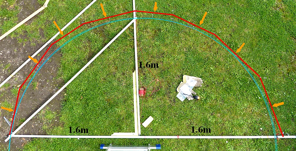
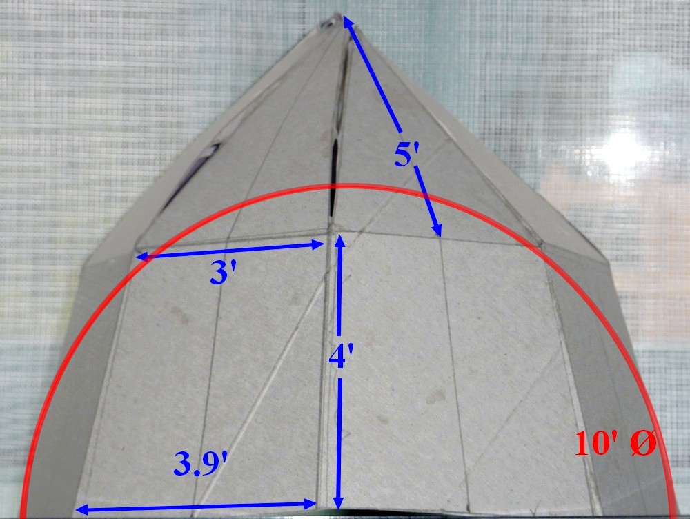
The
two ribs should actually meet at the top but I wasn't going to cut the
arcs just for a mock-up. I leaned the structure up against the octagon
and spread the base of the pretend "ribs" by 63cm as prescribed by
Geo-Dome's trapezium dome calculator. The red lines on the inside of the
distant rib are to simulate the flat panels. All of which, regardless
of size and shape, will be 63cm tall. But only 63cm wide at the
base ring.
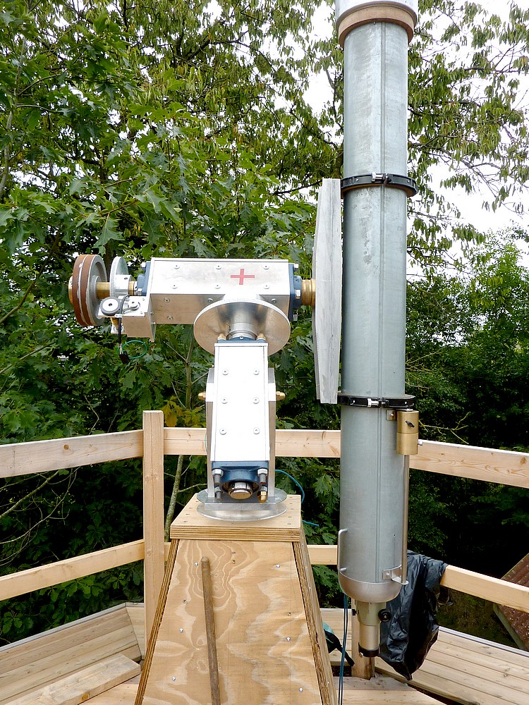
When seen
up close, like this, the dome shrinks into a manageable size. Up on the
platform a single arc seems so unwieldy that I can hardly imagine
erecting the complete dome up there. The old, aluminium satellite dish.
leaning against the shed, is intended to reinforce the observation slit
around the top of the dome. Probably protecting a laminated plywood
collar for extra strength.
The
next step is cut more arcs to make the ribs from 9mm birch plywood.
Which is seen stored safely under wraps against the side of the shed. Each rib will consume
one full, 1.5m arc with about another meter extending on top of that. With a
halving joint between them just as I did with the base ring. The
observing slit will save some length on the second, upper arc. Though I may
complete all the other ribs before constructing the observation slit.
With
the ribs ready, I can start cutting the horizontal cross struts, for
each level, from softwood. Probably using 2"x2" timber. The struts will need
compound mitering to fit between the ribs. Not only do the ribs radiate
from a central, vertical axis of the dome but the segments shrink
constantly as they head upwards, towards the pole. Provided I can
establish a pattern for each of the four cross struts I can cut more and
know they will fit exactly into the next segment along. In theory the strut
making should be a form of mass production. Not forgetting to saw two opposing bevels on the table saw of the outer surfaces for the panels to rest flat.
 A sixteen sided figure is a hexadecagon. The internal angles are 157.5°.
So the miter angle to be cut on the ends of the horizontal struts is 180
- 157.5/2 = 11.25°. This is the same angle which must be double beveled on the faces of the vertical struts. Which will be laid on the 'flats' cut away from the ribs. Both to
reinforce the ribs and provide a substantial bed for the flat,
trapezoid, 4mm plywood sheathing panels.
A sixteen sided figure is a hexadecagon. The internal angles are 157.5°.
So the miter angle to be cut on the ends of the horizontal struts is 180
- 157.5/2 = 11.25°. This is the same angle which must be double beveled on the faces of the vertical struts. Which will be laid on the 'flats' cut away from the ribs. Both to
reinforce the ribs and provide a substantial bed for the flat,
trapezoid, 4mm plywood sheathing panels.I have bought some 43x43mm timber for some experimental struts to make up a single dome segment. However, the continuing bad weather has stopped most work on the build. I need to be outside to have enough room to cut the 9mm plywood arcs for the dome from 5' x 5' sheets. It is not the matter of a few moments to tidy everything up between sudden cloudbursts. September 2017 in Denmark is heading for an all time rainfall record. There was more rain on one particular day than the average for the whole of a normal September. The weather has constantly flip-flopped between sunny and cloudbursts. The regular gales don't help.
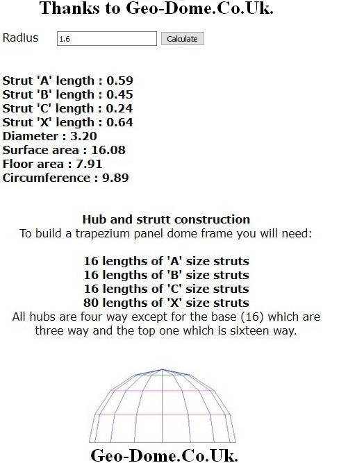
Thanks to Paul Robinson's Geo-Dome trapezium dome calculator
http://www.geo-dome.co.uk/trap_tool.asp
I can find the weight of the struts.
More information here:
http://www.geo-dome.co.uk/article.asp?uname=trap_dome
By a happy/unhappy coincidence 43x43mm softwood [pine] weighs close to 1kg per meter, or roughly 2.2 lbs/ per m or 39.4".
Vertical struts = 16 x 4 = 64 x 64cm = 41m
Horizontal struts = 16 x 64 cm = 10.2 m
16 x 59 " = 9.5
16 x 45 " = 7.2
16 x 24 " = 4
Total length of struts = 71m
Weight = 71kg or about 156lbs. Eek?
To which must be added the weight of the 4mm plywood sheathing, of course.
Click on any image for an enlargement.
*


