23.1.18

Going Solar H-alpha? [H-α] Starting point:

*
WARNING: SOLAR OBSERVATION REQUIRES GREAT CARE AND SAFE FILTRATION.
INSTANT PERMANENT BLINDNESS CAN EASILY RESULT FROM SIMPLE MISTAKES.
NEVER LOOK AT THE SUN THROUGH ANY LENS, MIRROR OR INSTRUMENT UNLESS IT HAS BEEN FULLY TESTED AND APPROVED FOR SUCH USE. YOU FOLLOW MY EXAMPLE ENTIRELY AT YOUR OWN PERIL!


Three weeks into January and not much ATM accomplished so far.
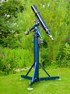
After waiting for 50 years I am rather keen to get into [low budget] Hydrogen-alpha solar viewing [and hopefully a bit of imaging.] My timing is highly imperfect with the Sun descending into its quiescent phase of its 11 year cycle. There is even talk of a spotless Sun enduring. Not to mention all the cloud in the Earth's own atmosphere.

My [wishful] thinking is that my raised observatory will provide much better seeing so far above the ground. Daytime viewing also keeps me out of mischief and at home. All without conflicting with an Evening's Netflix TV streaming.

I made my own spectroscopes literally from scratch back in my youth. Including making a pair of 60mm achromats and a high density, 60° flint prism. Closely spaced razor blades acted as slits and I could see literally thousands of lines in the brilliant [and occasionally blinding] Solar Spectrum.

Any plans for a mechanical spectrohelioscope at that time were dashed by a lack of a suitable grating. I spent ages researching at the reference library on how to make one. There was no internet back then and most books were long out of date.

Nowadays all I need for H-α viewing of surface detail and prominences is is a used [but not abused] Coronado PST with still undamaged, internal components. This will be used as a donor for modifying my old 6" f/8 Celestron to H-α. I don't really need the PST objective except for quick looks at the Sun to check for interesting activity.

I'd hate to spend serious money on an old and secondhand PST with a rusty ITF [blocking] filter. The new prices for the PST have doubled while I wasn't paying attention. With 10-year-old PSTs now listed at new, retail prices of only a few short years ago.

It would cost around £100 extra for a new replacement ITF [blocking filter] bought from the US. That's with import taxes, postal customs clearance charges, freight charges and 25% Danish VAT on top of everything, including the US retail price.

Then there's the cost of the 90mm Baader D-ERF [for heat rejection purposes] to go inside the big refractor. There's no real need for a full aperture filter to go in front of the objective. Being monochromatic in nature, H-alpha ignores the usual achromatic aberration of a 'fast' f/8  achromatic doublet. It will be automatically stopped down to 125mm by the small PST etalon. 1200/125 is much closer to the f/10 of the PST.

Here's a YouTube video showing typical images seen through a PST and the effects of software stacking to achieve very sharp, still images in Hydrogen-alpha light. Note the prominences and surface detail.


The H-α system relies on leading and trailing lenses sandwiching a special filter [the etalon] to pass parallel light through the filter. The focused light from the telescope objective is first made parallel with a negative lens at 200mm inside focus. Then refocused again with a matching positive lens after "conversion" [or very narrow band filtering] to H-alpha by the etalon in the middle of the group. H-α is a line in the visible, deep red of the Solar Spectrum.

This modification to a larger aperture refractor is well proven using the internal components of a donor PST. Providing excellent, high powered images at a small fraction of the cost of a dedicated H-alpha, commercial, solar telescope which run into the thousands of pounds/dollars retail for larger apertures. The PST is undamaged by the modification. So can be rebuilt to its original layout. A number of manufacturers offer special adapters for PST connection or even adding a star diagonal in place f the PST's internal prism.

My old, Fullerscopes MkIV equatorial mounting can easily cope with the 6" refractor on its massive, welded steel pier. I have used the combination regularly to take handheld "snaps" at the eyepiece without visible camera shake. I replaced the three, original 10" pneumatic, trailer nose wheels with solid, puncture-free wheels. These solved a number of problems of mobility and lack of damping in the original air filled tyres without compromising freedom of movement. 

----------------------------------------------

[It's odd but none of the published Alt key Codes work for α [alpha] in W10. Alt+ 224 and Alt +945 are listed online but neither works. Not even with a zero in front. It seems the only way to insert alpha is to Copy and Paste. Hey-ho. Hey (slow) presto!]

*

14.1.18

2018 New Year Dome build progress?

*
A couple of weeks into the new year there was an unusual combination of light winds and dry weather. The temperature is still hovering about freezing point.

So I dragged out some dome segments to have another look at providing an observation slit. Two long arcs of plywood and several 60cm struts gave me a basic, slit framework. In theory I should be able to scribe across the horizontal struts onto the segments either side of the slit. Cutting the struts off to the scribed lines should allow the slit frame to be slid into the dome structure and screwed into place. 

However [and there's always a however] the geometry of the mock-up might result in rather inaccurate marking. The slit cannot be physically inside the dome's surface and still miss the segments on either side. So it must be laid over the existing dome segments. Perhaps I should remove the horizontal struts and measure their new lengths and angles after the slit is fitted in place?

While trying to decide on suitable shutter[s] for the slit I originally thought I was going to use numerous shallow doors. With interlocking frames [like trays] for weather proofing.

Then I realized that horizontally sliding, split shutters [Palomar style] would still suit the angled geometry of my faceted [tetrahedral] dome. It would just require that the shutters themselves follows the angles of the tiers of the facets just like the rest of the dome. No doubt the shutter facets would each need to be slightly deeper than the dome because they were being overlaid.

Here's yet another mock-up with the slit frame resting on top of the clamped dome segments.The main problem is that a beyond-the-zenith, cut-out would require shortened ribs. With the result that the [clamped] dome would no longer be self-supporting without the slit frame already fixed in place. Another of those chicken and egg problems.

Then I imagined a square frame carefully supported and centered at finished dome height. The ribs could then be carefully marked and cut away to match this frame. Allowing the slit frame to take its rightful place once the segments are all accurately prepared.

Such a shutter arrangement has several potential advantages: Including improved weather proofing and no small, flapping doors, each requiring secure fasteners. Plus the ability to open one half shutter and leave the other closed for better wind protection.

Rain should run down these full length shutters just as well as the rest of the dome. Without intervening rain-collecting ledges. As might well occur with small doors. If done properly the closed shutters should offer the least offense to the eye as a discontinuity of the overall form of the dome. The overlap between the two shutters would obviously need attention to stop rain from driving between them. The shutters would slide horizontally on stainless steel pipe firmly fixed at the skirt and the over-the-zenith frame.


*

3.1.18

Mounting update: A better way of securing the Dec drive cables:

*

After further fiddling I came up with another way of running the motor cable. The sturdy, aluminium box, in which the stepper motor sits, has empty corners where the motor body is cut away. These radiused slots are obviously to provide direct driver access to the motor's fixing screws.

None of the plugs are easily removable from their cables. So gaining access to the corner channels required notches and the cable fed carefully through the box as the motor was gently slid back into place.

Once the cable and socket had reached the correct orientation I clamped the plug down with a simple metal  bridge and long screws fitted with Nyloc nuts. Again, I had to use countersunk head screws in internally countersunk holes to allow the motor to fit inside its nicely cosy, tubular box casing. Normal screw heads would have protruded and blocked the motor from entering.

[Note how I have used screws and oversized washers to capture the loose journal bearing in the Beacon Hill worm housing. At left in the image above. The bearing used to constantly work itself outwards during Dec slews but is now perfectly secure. I could have tapped more, radial, threaded holes for more grub screws but decided against this because they distort the bearing outer race and increase friction. As I discovered when I tightened the single [original] grub screw to try [unsuccessfully] to stop the bearing falling out all the time. The bearing simply locked up solid!]

The main Declination cable is provided with a loop and fixed to the PA with a zip tie for strain relief. A P-clip keeps the short, motor attachment cable from becoming untidy. Normally, the black plug and socket are all but invisible under the Dec motor support plate. The images show the progress so far.

The Polar Axis, motor housing does not move so needs no cable slack for long slews. I have P-clipped the plug and socket out of sight under the RA motor, support plate, for protection. The image [right] shows the much tidier drive cable arrangements. I'll be glad to see an end to the chain hoist appearing in every picture! I have to keep the hoist chain  taught just in case the mounting support collapses. As has occurred twice now! The mounting's own weight is prodigious even without a telescope and counterweights fitted.

Click on any image for an enlargement.

*

1.1.18

Mounting update: Securing the cables to the Dec motor.

 *

 The image shows the latest arrangement of the Dec stepper motor drive cables. Not easy to photograph underneath the Dec axis, motor support plate in a dark shed/workshop.

I decided the initial motor cable was far more fragile than the long, sleeved cable connected to the AWR Microstep Drive box. Both cables are joined by a unique, latching, plug and socket.

The initial cable was also rather long for my own needs. So I folded and zip tied it to the edge of the 10mm thick, motor support plate. Though not very tidily, I admit. I still haven't earthed the green wire until fully satisfied with the cabling arrangements. I may still fold the motor cable under the motor support plate to hide it better.

I then P-clipped the heavier connecting cable to act as the cable's, strain relief device. This much sturdier cable goes through the large hole in the mounting's fork face plate and thence off to the AWR electronics. AWR were very generous with these connecting cables to allow for a very tall pier for the refractor and/or some distance to the drive electronics.

It is important that no load is placed on the short, initial, motor cable as the mounting moves the telescope around the sky. So I have added a slack loop of the heavier cable to allow for 180° of Declination axis rotation. Not to mention catering for a similar range of PA movements.

I used to park the folded refractor horizontally on the north side of the pier with the weights up on the south side. [Image right] This was only to reduce wind loading on the temporary pier in case it all tipped over during a gale. I doubt I shall have to resort to such "gymnastics" with the long telescope tube safely housed in its dome. Though I may yet revert to the folded form.

I don't have a name [yet] for the black, 9 pin, latching plug and socket. The AWR guide mentions a rectangular 'Quick-mate' system, but I haven't found any images online to confirm this. I thought I might be able to shorten the first motor cable myself, to tidy things up, if I can source a spare socket.

This will save me purchasing a complete, but shorter motor cable from AWR. Though there could easily be some soldering or crimping of the wires to the pins and sleeves involved. I haven't discovered if the plugs and sockets can be disassembled. Or even re-wired after use without destroying anything. Only six of the 9 pins available are actively used.


Click on any image for an enlargement.

*