29.4.18

Dome building: Resurrection.

*
Friday and a bank holiday. I glued all the vertical struts to the ribs using outdoor white wood glue. I have been very hesitant to use glue until the structure is proven to fit together.

Saturday: Re-leveled the base ring and rebuilt the dome. This time with the observation slit nearest the shed door. Hopefully this will save me having to walk right around the dome just to get inside. Now I have reached this point I ought to lower the base ring. It really doesn't have to be this high. I still don't have enough clamps.

Sunday: As I had reversed the dome on the base ring I thought I'd better re-check the geometry. So I ran a long cord back and forth between each pair of ribs to find the dome's exact center. Having planted a central pipe, as a marker, I dropped a plumbline [just visible in the image on a red cord] from the center of the top slit beam. This proved that I had serious level problems. So I ran a heavier rope up to the octagon fence to pull the slit frame upright and level at the top. A diagonal, internal, timber prop would only have got in the way.

Later I went round checking the distance to the central pipe from the inner curve of the base ring. The pipe was about 1.5" off center. I need to find a sturdier steel pipe which I can drive more firmly into the ground at dead center.

With the slit's top cross beam still too high I decided to lower the entire dome on its stands. This would hopefully make it much easier to get in and out. There followed an hour going round and round screwing down the metal jacks and adjusting the timber props. Finally I had the base ring level and almost as low as it will go on the stand screws.

The slit clearance at the zenith was now a miserable 2.5" according to the plumbline. For some reason the slit frame does not want to tip inwards and downwards to increase the clearance beyond the zenith. I presume it must be the two attached gores holding the slit frame upright. I tried pushing the base beam inwards but that didn't help either. I even double checked that the opposing central gore was not resisting my efforts. I shall now have to try unscrewing the horizontal struts on either side of the slit frame.

As can be seen from the overhead view I eventually managed to sink the slit frame slightly but not to increase the clearance at the zenith. I also added another 2x6 on a 2x8 base, timber prop. To help reduce the risk of the completed dome becoming unstable on its stands in high winds.

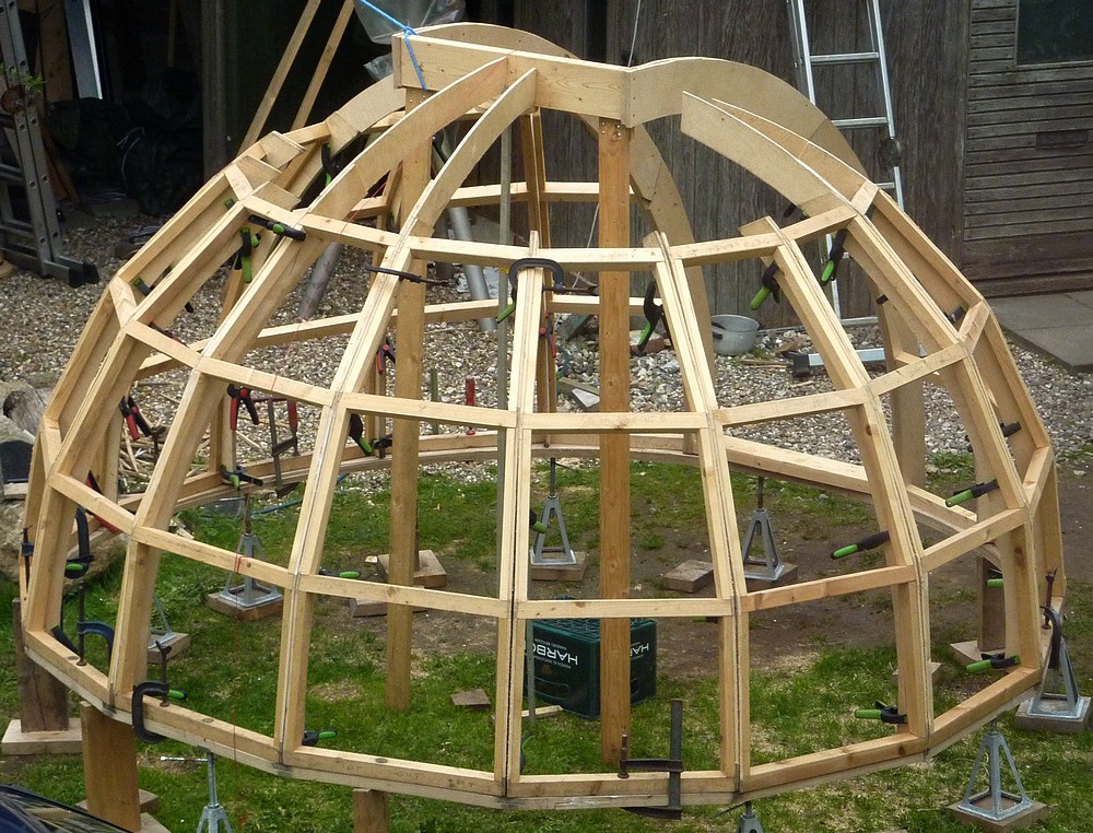
The image [right] shows how sturdy the dome now appears. I think I will move the taller gores away from the slit. In their present position they offer almost no support to the unnextended  gores. So the whole dome is sagging inwards at the top. Which leaves small but visible gaps between the ribs.

If only I had a lot more C-clamps I could close the gaps to lift the gores to their correct form and position. Fifteen times even small gaps soon adds up. Which distorts the overall shape of the dome. The plywood isn't thick enough for wood screws to bring the ribs tightly together.

The dome seems to have assumed a slightly different shape since I fitted the heavy, observing slit frame. My intention is to make the dome symmetrical and then refit the slit frame. Symmetry is important to sizing the trapezoid, covering panels.

I am quite tempted to buy a lot of nuts, washers and bolts to hold the gores more tightly together. This would be far cheaper than buying a lot more clamps. The bolts could be passed through the plywood ribs just inside the vertical struts to exert maximum pressure where it really matters. Even at three clamps per rib the spring clamps don't have the power to pull the dome really tightly together.

I'd need about 60 nuts and bolts and 120 oversized, load spreading washers. I have now placed an order for 100 M6x30mm, A4 stainless steel, hex socket head screws, oversized 18mm [3/4"] washers and matching nuts. I tested one 6mm coach bolt and 14mm washers and seemed not to pull themselves into the birch plywood. 18mm washers will further reduce any such risk.

Wednesday: Drilled the ribs and fitted the nuts, washers and screws to hold the dome together. Four screws per rib = 14 x 4 = 56. So I have nearly half left to add more screws if desired. The dome is now completely self-supporting without any clamps at all. It just needs the slit frame to find its natural place with some clearance at the zenith. That will require the opposing gore ribs to be carefully trimmed back. Then I can add all the other rib extensions to secure the slit frame properly.

It is interesting how the strut dimensions dictate the shape of the dome. It cannot adopt any other shape because the dome refuses to be distorted. Raising a ring of horizontal struts would produce another shape unless they were each shortened to match their new place. If the struts were lowered on the dome's surface they would become too short for that latitude. Causing distortion and quite possibly refusing to come together at the ribs.

I wish I had been more aware of this when starting out. I would have concentrated far more on achieving perfect uniformity of strut length. I was relying on the curvature of the ribs and fitting struts to match their actual spacing. The ribs certainly helped as a guide but they were too flexible and could  distort sideways if a strut was not the perfect length. Adding the vertical struts last fixed the latitude of the horizontal struts.

Click on any image for an enlargement
*

24.4.18

Dome building.. and un-building.

 *

I spent the morning cutting more vertical struts and fixing the levels of the horizontal struts to match.

Then I decided it was long overdue that I cut the base ring flats. So I ran a broad pencil along the base struts and then dismantled the dome. The gores take only about five minutes to un-clamp and move them out of the way. The slit frame is a bit weighty because of the added gores on either side. So I lowered it halfway onto a stepladder. Then down onto the ground. It was manageable after that.

I sawed around the base ring cutting off the overhangs with a jigsaw. The dome needs to shed water so a round base would make a complete mess of the dome's 16-sided skirt. Now the lower panels can safely overhang the base ring.

The next step is to mark the center of the base ring and run a router around to make it smoothly circular. There were also some overlong screw points to smooth away from underneath the rings. Finally I can add a layer of oil treated hardboard beneath the ring as a smooth running surface.

Wednesday: I checked for ovality with the cross in place using a beam compass. Then I added my cheap, Chinese router to the radius arm. It felt solid but was not stiff enough. When the router bit dug in it caused waves on the running surface. So I added a second beam to make an A-frame. With the pivot on the top point of the A. If I was doing this regularly I would have added fine adjustment for radius using a cross drilled stud at the pivot. [All thread].

After a pause for rain and lunch I returned to routing. The problem was the cross of boards I had used for bracing. They stopped the router from allowing a bearing guided trimming bit to run freely right round. Another Catch 22. I couldn't lift the ring without its supporting cross. Nor, later, when I wanted to lift the entire ring up to test it on the dome supporting rollers. Then the big mounting was in the way when I wanted to fit the ring with the cross still in place.

Then it started pouring down with hale thrown in. I tidied my tools away and abandoned work for today. The ring is safe draped partially over the rollers. I shall have to remove the Torx screws to rid myself of the cross braces before I can lower the ring onto the rollers. Even then I still have some routing to do.

If only I had the wisdom of perfect hindsight! I could have moved the crossed braces into a rectangular form. Then I could have finished the routing down on the ground. Before lifting the ring upstairs and easily over the big mounting.

Thursday: It's bright but breezy today so I shall start by relocating the cross braces. I was soon able to get the ring on top of the rollers. A couple of minutes with the router removed the uncut overhangs. After that the ring turned effortlessly on the rollers.

I moved one skateboard steering wheel towards its roller and then lowered the ring back down  to the ground with parallel braces. Not nearly as good as crossed braces. All the while it kept blowing, raining and hailing for a few seconds at a time.

Click on any image for an enlargement.
*

20.4.18

Dome building: Framing the observation slit.

*
Having cut the ribs, to frame out the observation slit, I laid it over the dome's skeleton. Cutting back two of the three, full height gores allowed the frame to rest on the last gore opposite the slit.

The frame still looked too tall as if projecting too much above the dome. Nor did the remaining gores want to match the internal radius of all the ribs. There should be an unobstructed, hemispherical space inside the containing woodwork. Any projection might spell disaster for the enclosed telescopes or mounting drives in a collision.

In an attempt to stabilize the slit framework I used some battens and boards to support it from the ground. Further marking and sawing produced more 16mm thick arcs to reinforce the slit frame. Choosing where to break the arcs to avoid local weakness of the necessary joints needs some thought. The arcs remain lightly screwed and clamped together while I decide how best to proceed.

Fortunately the forecast remains dry so I have no real need to cover the skeleton. Nor its foolishly projecting timber props. I'd rather not cut them off unless absolutely necessary. The horizontal bar half way up the slit is only temporary and designed to allow me to duck easily inside the dome. It is important that the slit frame is parallel, symmetrical and square while the dome's skeleton is joined onto it.  

If I can arrange the observing slit frame at a suitable height I can start tying in the gore ribs by adding extensions. I need to bring back the strength missing from "cutting out" a huge hole in the dome just to be able to see out. Horizontal struts will need to be tied into the nearest ribs once they have been doubled for strength. Then vertical struts will be added to provide a supporting surface for the trapezoid cladding sheets.

The dome is already remarkably strong considering it is simply clamped together. I was easily able to climb up the horizontal braces to place a builder's level across the top batten of the slit frame. Once the ribs are glued and screwed together it will gain remarkably in strength. Then come the trapezoid panels, glued and screwed on top. These will add a stressed skin effect to resist the skeleton from twisting.

Saturday, I spent some time cutting out 16mm arcs for the slit frame. Still two, half arcs short of a set. I just found a 5'x5' of 16mm birch in my plywood stock which I had completely forgotten about. It has survived the winter with some darkening along one edge. Fortunately I needed only two shorter arcs so I could avoid the staining.

Sunday, I doubled the arcs with offset joints and 2"x6s" top and bottom. Now firmly propped, independent of the dome to ensure the slit frame  is central, the correct height and level. Rain and showers are forecast so I have covered the dome in lightweight tarpaulins to keep the worst off.

Monday, I cut six horizontal struts to join the slit arcs to the nearest [doubled] ribs. This was quite time consuming because the compound angles changed with height. Lots of to-ing and fro-ing between the miter saw and the dome. Taking small cuts allowed me to sneak up on the required length. I am still using up 40x40mm batten off-cuts from earlier in the build. So wastage has been minimized.

Tuesday offers gales and rain. I may be able to work on the dome when it brightens up later.

 Click on any image for an enlargement.
*

17.4.18

Dome building: Procrastination.

*
With the dome sitting there in the sunshine I had to decide how best to incorporate the observing slit frame. This is an important component because it seriously weakens the dome by inserting a big section of fresh air. Where the rest has lots of seriously stiff woodwork. 

I found some remaining 16mm birch plywood which was left over from making the base ring. Doubled, it will bring the thickness to almost 1.5". Which should be enough in a 15cm, 6" deep rib to safely support all that fresh air. The joints will need to be offset for strength and the two rib arcs well screwed and glued together.

Meanwhile some alternative views of the dome's progress:  

The ribs are now nicely reinforced by the horizontal and vertical struts. With greatest depth of rib at the strut joints where it is most needed for strength.

The dome is self-supporting just resting on the base ring. Each pair of gores is held by a single spring clamp at the top of the ribs.

Wednesday 18th and I only worked for a couple of hours on the dome. I cut new slit framing ribs in 16mm birch plywood. The arcs had to be drawn with a home made beam compass for accuracy. I allowed 2" external overlap and four inches extra depth to bring the inside radius to match all the other ribs. Which meant 6" overall depth. I should have just enough 16mm ply left to produce two doubled arcs for 32mm overall thickness. The joints will all be offset to avoid local weakness.

The next step is to cut the full height gores to allow the slit frame arcs to drop down to the correct height at the top. I am trying to make the shutter doors as low profile as possible. While maintaining the same faceted appearance of the rest of the dome for a uniform look.

I kept cutting back the tallest gores to allow the slit frame arcs to just drop between them without distortion. Then I added extra props to stabilize the frame. Eventually the frame was resting centrally on a 2"x2" marking the end of the frame 6" beyond the zenith. I could then screw the partial arcs of the slit frame together. A long level was placed across the top batten to check it really was level.

Earlier I had unwound the "corkscrew effect" on the upper ribs from adding the vertical struts. These had lifted the original horizontal struts just enough art the third tier to make them slightly overlong relative to their latitude ring on the dome. The 1/3 tier of horizontal struts were removed and run through the miter saw to bring them all to a slightly shorter length. It was easy to match the compound miters by pressing a pre-cut strut end against the saw blade and then adjusting the miter saw settings to close any air gaps.

Once reassembled the ribs were now all upright without the previous kinks at the third tier. I continue to use Torx screws, without using any glue, so I can step backwards to undo any mistakes. The Torx screws only rarely fail to undo provided the driver bit matches the socket and is unworn.

The last image shows the slit frame and ribs stabilized with struts down to the ground.  Further struts lift the longer gores to match the slit ribs. I could then clamp extensions of the dome's plywood ribs up to the slit framework.The 2x2 batten is supposed to represent a 2" lift above the dome but looks far too high.

Click on any image for an enlargement.
*

Dome ongoing: See saw, mind the door.

*
I was struggling to close the gaps between the gores due to a lack of clamps. The ratchet straps didn't help much because of the gap for the observation slit.

Mid morning in sunshine and my 71st birthday present arrived in the form of a DE7400 DeWalt mobile workstand for my table saw. Mobility was certainly achieved once I finally had put the thing together. 

DeWalt's instructions book artwork is all but useless. Small images, with thin grey lines instead of solid black with enough substance to see it without a microscope. It really is unforgivable. As is not duplicating the images for each language. Are they really afraid of the cost of a couple of extra printed pages? Fortunately I don't need instructions but hate making obvious mistakes when all logic has escaped the maker.

When it came to squeezing the table saw under the miter saw on its own stand I hit several snags. The worst was the completely unnecessary carrying handle on the underside of the miter saw stand. This required I lift the whole miter saw and its bench one handed. While I wriggled the table saw carefully underneath.

Then the yellow ends of the miter saw bench stopped the table saw fence bars from going under. More wriggling as I lifted both the miter saw and bench saws bodily lengthways. Finally, I was able to nest the two but it used up a lot of depth in my 8' wide shed space. The saws face a 30" deep shelving unit.

 I you close one eye you can't see the mess surrounding the nested DeWalt saws. Pushing the tyres with the flat of my foot proved useful to get the table saw to creep gently under the miter saw bench. I really don't need such a long bench for the miter saw but anything shorter would block the table saw on its mobile bench. Two mobile benches side by side would work [at considerable extra cost!]

Placing the table saw on its bench nearest the wheels, so that one support bracket is nested in the bright, pressed steel bracket, greatly helps the balance when wheeling the saw about. The retractable handle provides just the right leverage for almost effortless mobility. I was very pleased with this aspect. It will save me crippling myself by bodily lifting the table saw, from the floor and onto a static workbench outside every time I need to use it. I am a martyr to mental inertia when it comes to such hurdles.

The only obvious downside is the considerable distance covered on the ground when lifting and lowering from and back onto the wheels with the legs extended. The stand and mounted saw have to rotate around an arc centered on the feet of the forward legs.

Lifting the loaded, table saw bench on and off its widely splayed legs looks awkward but is easy enough. Even for a fully certified old fart like myself. The DE7400 mobile saw stand is highly recommended by this new user.

Click on any image for an enlargement.
*

16.4.18

Dome observing slit width:

*

The recommended observing slit width is 1/3 the Ø of a dome. 3m / 3 = 1m wide. So I cut two battens to space the slit frame to 1m instead of the former 60cm. [2']

To my mind it is aesthetically displeasing. More like a barn door to let a horse and carriage through. Though it doesn't look quite so bad from inside the dome. I took the image at an angle to show the slit framing ribs more clearly.


Here's the same dome with a 2' spacing across the ribs. I feel this looks more normal. Perhaps a little mean. Dome owners warn against making the slit too narrow. Or the dome needs to be moved to often to follow an object. [Assuming manual dome rotation] A narrow slit hides a lot of sky making it more difficult to find constellation and objects. It also blocks stray light and the wind better.

I think I'll try spacing the slit ribs at 90cm or ~3' apart just to see what that looks like. It doesn't cost anything except a couple of lengths of batten at this stage.


90cm didn't look much different from 1m. So I tried 80cm.  I think this looks nicely balanced against the overall dimensions of the dome.

BTW: None of the slits is supposed to be symmetrical with the dome structure. I just laid the frames over to take some pictures. 

I clamped the upper ends of the gores together to hold the dome up. It seems quite stable just relying on friction alone.

Click on any image for an enlargement.
*

14.4.18

Thickening and raising domes:

*
After four days of gales the wind has fallen light but it is drizzling lightly now and then. After cutting 40-odd braces I realised I was mistaken about them being reversible. So I had to mark L&R and cut one end the opposite miter angle. Fitting longer tilt stop screws to the DeWalt compound miter saw allows me to flip-flop the blade by 5° each way without needing to release anything. So it didn't take long to correct without changing the length of each strut.

I decided to cut down the strut dimensions to save some weight on the completed dome. 120 of anything soon adds up. Even the thin, off-cut strips weighed quite a bit.

By ripping the 20x90mm boards with the table saw blade tilted at 10° I get a pre-cut profile. The pile of sawdust is certainly building quickly.

I'm working inside the shed with the miter saw to avoid having to carry it in and out. It weighs far more than I care to manage at my age. The table saw is more manageable and much less awkward. I store it on the floor and sack truck it back and forth. Which leaves only one big lift up onto the B&D folding workbench. There is a DeWalt, hydraulically assisted, rise and fall bench. With wheels like a built-in sack truck but it's not exactly cheap! If it saves me from a back injury then it might be worth having.

Well, the hydraulic bench had an awful review so I gave up on that. Fortunately there is another bench, with handles and sturdy wheels. Designed to make transport easier over a building site without having to demount the table saw. The DE7200-XJ is cheaper and lighter too. There are several YT videos which indicate it is probably a much safer purchase than the rise and fall model.

Sunday 15th April found me still cutting and fitting vertical struts. I used a clamped stop on the miter saw to trim each strut to exactly the same length. This had the advantage that it forced the horizontal struts to become better aligned and horizontal. Though I had to unscrew several of them the overall accuracy wasn't too bad to start with. Some just needed the strut to be tapped home with the loaded plastic hammer before screwing it into place with 25mm [1"] csk stainless screws.

Rain stopped play just as I put the last screw into the last strut. The upper [third] tier was difficult to reach so I took the gores down to work on them one at a time. The skeleton is looking far more chunky now and should have remarkable resistance to wind and snow loads. But now I can't fit my spring clamps over the paired ribs and vertical braces. I'll try ratchet straps and friction when I need to erect the dome to work on it. A week of warm and sunny weather is forecast.

Next I'm going to use a rough disk on the angle grinder to trim the ribs neatly back to the level of the struts. The jigsaw I used to cut the flats on the ribs was pretty rough at times. I used a scribed guide line for each cut but the saw wandered a bit. 

Click on any image for an enlargement.
*

9.4.18

Teleskop-Service 1.25" 90° star diagonal arrives.

*

The post arrived, while I was busy on the dome, bringing a 1.25" 90° T-S star diagonal from a UK dealer. It was much better quality than my no-name examples from several years back. Most importantly, it had a compression band eyepiece holder and a decent sized thumbscrew to get a firm grip on the binoviewer nose-piece. The diagonal is delivered in a posh, textured cardboard, presentation box. With a cut-out foam box filler for protection.

I briefly tried the binoviewer in the star diagonal and, as expected, it was securely held by the diagonal's compression band.

However, once the GPS was fitted it proved physically impossible to clamp the nose-piece of the binoviewer itself, even at full depth. I had to lift the binoviewer just enough to completely clear the compression band. The diagonal then held the GPC directly. Being of sturdy aluminium build, the GPC can be safely held by a compression band. Though it does require that the GPC is screwed firmly to the binoviewer to avoid any unwanted movement.

The technique is to tighten the diagonal's compression band just enough to prevent the slightly larger, binoviewer nose-piece from entering. This automatically stops the binoviewer from dropping down too far and leaves the GPC at the correct depth for secure clamping. The lower, right image shows the binoviewer nose-piece completely exposed after GPC clamping.

The T-S diagonal's eyepiece holding section is easily unscrewed. So, the binoviewer nose-piece is being held by a very similar sized screw thread to that of the diagonal. The GPC + binoviewer is just one more thread in a whole series, literally holding everything together. Any weakness in the system is [probably] largely psychological. Provided, of course, everything is screwed on firmly, but only hand tight. Tools are not desirable for this task.

I must admit that I still find the unwanted and undersized GPC extension a design flaw. I would much prefer the heavy binoviewer, with its two low power eyepieces, be properly supported by its own nose-piece. Even if only partially. Avoidance of unwanted extension is provided if one simply leaves the GPC off.

Which is exactly my plan as I build a terrestrial 90mm binoviewer telescope for typical spotting scope powers. Rather than, more typical, astronomical powers.

Where full, binoviewer nose-piece seating, with GPC, is desirable then a 2" star diagonal can be used with a 2" to 1.25" adapter. Though here clearance for the physically sensitive mirror must be carefully checked. Or the binoviewer + GPC can be used "straight through" in a 1.25" focuser without a stop ring.

Click on any image for an enlargement.
*

Spring has sprung the dome is ris[en.]

*

As it was hovering around 60F [15C] I decided to make another start on the dome. The last time I tried to glue anything it turned snowy white and didn't hold. So I put off further work until the spring. Since I have to work out of doors the long cold winter has delayed progress more than I would have liked.

First I had to take down the dome base ring which had been leaning up against the octagon building over the winter. All the screws had to come out again to allow the two layers of birch ply to be separated.

Then I applied a line of fresh construction adhesive at each adjoining edges and a wavy line in between, to each lower arc. The second layer was then laid on top and the two screwed together. Followed by all the clamps I posses. I then added further 25mm [1"] screws to ensure it was all as solid as possible.

The forecast is for only 41F [5C] overnight so I shall lift the ring off the ground on wooden blocks and cover it in several layers of lightweight tarpaulin.

Or not. I was keen to frame out the observing slit on the  dome. So went ahead and rebuilt and clamped the dome. The frame of the observing slit is 60cm [2'] wide and overlaps the zenith.  The cross strut is only temporary to ensure the slit remains square and the correct width.

Now I see the frame in place I realise that I should have made the ribs twice as deep. Just to have something to which to firmly attach the normal ribs for strength. Not to mention closing off the dome against the weather on either side of the frame.

Originally I was going to have an up and over shutter but then decided to go with small overlapping doors. The faceted sides don't really suit a bi-parting shutter. Horizontally hinged doors seemed the only way to build a shutter which closely matched the rest of the trapezium, faceted dome.

Perhaps the shutter could still be made flush with the dome rather than projecting? Though I don't see how the hinge gaps could be safely sealed. If the slit frame is projecting then the hinges and the edges of the doors can overlap the frame to form a seal. A sponge draught seal strip will help here.

Tuesday 10th April 55F and gales. I decided to cut the flats on the gore ribs. The shorter gores went quickly enough: 10 x 2 x 3 flats. Plus 3 full gores of 3 x 2 x 4. The image left shows the stack of short gores already cut. The three full gores have yet to be taken down and cut. I use these three to support the dome while I am putting it up.

In fact all the gores are identical except that the short gores have yet to be extended beyond the limited sheet width from which they were cut. The wind makes the sawdust fly everywhere despite standing with my back to the wind. It is exhausting to spend so many hours out in it.

Wednesday 11th, 50F, Sunnier but just as windy. Finished cutting flats on the outer edges of the ribs for the covering panels. For some strange reason the dome now looks smaller. Perhaps the eye can more easily lock onto the flats than it could with more featureless curves?

I had planned to cut vertical braces with inner slots [dadoes] to lie over each pairs of ribs. This would provide greater strength against vertical crushing loads like snow and very strong winds.

Thursday: Decided to cut side mounted profiles on the table saw. By cutting on a miter I was able to obtain the correct slope for each gore at one cut out of 18mm x 90mm. 

Click on any image for an enlargement.
*

6.4.18

Going H-alpha: 2018, April 6th. A sunny day and 53F!

*

A clear, sunny day with only a little cloud coming from the west. Set up my modified 6" f/8 H-alpha telescope [125mm f/10 equivalent] on the big mounting up on the observatory platform. Sharpest views so far! One prominence was so razor sharp it looked like shrubs at the bottom of the garden. Tremendous detail in the largest prom. Which developed throughout the day as I tried various eyepieces.

The Sun's surface features were also sharper and more even than before. Though picking out detail was a matter of tilting my viewpoint. I had another go at tilting the D-ERF too and was pleased to see the background red blush had diminished slightly.

Throughout the day I took handheld snaps with the Canon short zoom. Still not a patch on what I could see visually.

Later I tried iCap with my Neximage5 but it was months since I last tried it and I had forgotten enough to make it pointless. A new iCap software edition is also available. The sky grew progressively more milky around the sun so I took everything down again at 5pm after spending hours trying different things.

I am amazed how well wireless works so far from the house and the indoor wireless router. No problem at all watching a trial UHD 4K video on YouTube on my 4K laptop. What was difficult was seeing anything on the screen in bright sunshine. Even with black backgrounds reflected in the screen it was a real struggle. So, I need a proper enclosure to make the laptop useful for solar. Not to mention providing shelter and a working surface when observing after dark. I still prefer a 'proper' mouse to the touch pad.

I think I'll hang something on the northern side of the pier. Where I can view the laptop inside a box. The top surface can act as a [rimmed] shelf for all the bits and pieces I need at the telescope. Presently, there is far too much climbing and descending the ladder to fetch things as they occur to me.

I have several clear plastic boxes for housing the drive electronics and optics [separately] with lock down lids for carrying them up and down. The telescopes have to be carried up and down too, of course. I also have to remove the cradle to allow the protective covering to lie compactly over the mounting. The Tollok bush stays safely in place on the Dec shaft after I remove the ten [cradle] fixing screws with a hex key.

The bush will only let go of the shaft if the special screw holes are used to push the compression/expansion cones apart. A nice safety feature which allows repeated dismantling without damage or risk. It takes far more torque to release the bush than to tighten its 10 clamping screws. I swapped the original screws to stainless steel, hex socket to avoid the inevitable rust. Though the Tollok bush is plain steel it has mostly resisted rust provided it is covered.

Sunday 8th was another sunny day of my staring at the sun in H-alpha. Much less detail to look at today. There was one, light fuzzy patch and a dark wavy line on the surface at 8 'clock and only two small prominences at 12 o'clock and four. A tall, barely visible, narrow jet rose vertically at about 3 o'clock in my star diagonal view.

*

5.4.18

Binoviewing: Reaching focus by tube chopping?

 *

The irony is that the Vixen original eyepiece holder was short enough at 20mm high to allow the binoviewers to reach focus with 26mm Meade 4000 Plossls in place, but with no GPC fitted. In fact there was about 5-6mm spare drawtube showing. Close, but good enough. While the binoviewers would not quite focus by roughly 4-5mm, with the 30mm high, Baader adapter fully lowered, unless I shorten the telescope's main tube.

After I fitted the GPC there was now plenty of drawtube to spare at focus but the image was magnified by about 2x. [At a very rough guess] The image was still surprisingly sharp for an overcast day. I was able to clearly see the buds on the trees at 450 yards and recognise [inverted] Fieldfares resting briefly in the same tree tops.  

Before I decide whether to chop the main tube and by how much,  I ought to seriously consider using a star diagonal. Which has more light path to take up if I should want to use the binoviewer for lower powers without the GPC. My 45° Baader Amici prism would provide an excellent erect image binoviewing experience if room can be found for it in the light path. Searching online has still not shown its optical path length. This ought to be standard information in the description.

The Vixen focuser is 12.3cm long from the end of the main tube when fitted with the Baader 1.25" adapter. I then removed the focuser and measured the focus point of the binoviewer from the end of the bare tube. When measured 'straight through' the focus was at 12cm. With one of my no-name 90° star diagonals the focus was 4cm from the end of the tube = 8.3 cm optical path length. With the Baader 45° diagonal it was at 1cm. = 12.3 - 1 = 11.3cm optical path.

This confirms the optical path length of each extra component. The binoviewer will not quite reach infinity focus with the Baader adapter in the focuser. So the extra 3mm inward movement required matches my early guesswork. To be able to use the binoviewer in the focuser with the 45° diagonal I will have to cut the Vixen's main tube about 12cm shorter to be on the safe side. A little extra margin of freedom is always valuable in case eyepieces are not all parfocal. From past experience it is only rarely I want to look straight through the Vixen.

The problem is that once it's main tube is "chopped" the telescope can no longer reach focus with a single eyepiece. At least, without using a diagonal. Would I ever want to view anything so low as be be comfortably seen inverted [upside down] with a single eyepiece? An inverted image is hardly useful for terrestrial use.

However, cutting 12cm from the Vixen main tube is very likely to cause serious vignetting by the very long drawtube when moved inwards. Causing the equivalent of a smaller aperture.

Unfortunately none of my 'scrap' aluminium tube is of suitable diameter. The Vixen main tube is thin wall and around 90mm. I have 80mm and 120mm tube but nothing in between. The Vixen objective cell is threaded onto the outside end of the tube. While I could [theoretically] cut a new thread in the lathe I can't manage such a long tube in my lathe. Though I could rig up a temporary tailstock to run in a plug. That would allow me to cut a thread.

If only I had some 100mm Ø tube I could turn some packing rings to join the two diameters to hold the objective and the focuser in place. Postage for half a meter of 100mm aluminium tube from eBay is three times the price of the tube itself! The tube is quite affordable. After endless searching I still haven't found a single, Danish aluminium stockist which will deal with private customers. Yet there are lots in the UK and Germany advertising on eBay.

After checking again I realised that only a male threaded, 90mm Ø tube, like the original, would be sensible. The small flange on the Vixen cell prevents a smaller tube, than 120mm Ø, from fitting over the cell.

Unless, of course, the cell is reversed to fit neatly into a 100mm tube. That would provide firm support and hopefully, proper collimation from the long, cast sleeve which normally supports the dewshield. The objective lens would be reversed, inside its cell, to point the correct way.

A packing ring on the outside of the 106mm section, on the cell, would support a 120mm dewshield. That would leave the far end of the 100mm tube available for a shorter focuser which would not cause vignetting. Possibly even a 2" focuser for extra stiffness. Though would mean considerably increased weight and bulk.

Whoopee! I just found 1m of 100mm Ø x 2mm [wall] aluminium tube online from a most unlikely online source. Order confirmed for home delivery and cheaper than buying from abroad. 😊

Click on any image for an enlargement.
*

4.4.18

Binoviewing partial success:

*

I was rather scathing about the T-S binoviewer GPC because it was slightly undersized at 31mm. I found it impossible to grip it safely in my original Vixen 90M focuser with its tiny thumbscrew. [Left.]

Further online research and careful measurement provided a direct screw-in option in place of the original eyepiece holder. The adjustable Baader adapter 1.25 Ø : 36.3mm thread fitted the Vixen focuser ring to perfection. [Right.]

The grip provided by the three clamping screws and the compression band now allowed me to lift the entire telescope safely off the ground! [Left] Where the single, small, Vixen thumbscrew could not even stop the binoviewer flopping about. The Baader adapter also has no stop ring so the binoviewer can be slid right in with the GPC still in place. Another hurdle safely cleared.

GPC = Glass Path Corrector. A form of compensated Barlow lens.


 These two images show the 5-6mm adjustability of the Baader adapter. It is really a short range helical focuser. Handy if one needs fine adjustment in a tight spot. A locking thumbscrew is provided to aid turning the focus ring and to lock the final adjustment.

After I fitted the GPC there was now plenty of drawtube to spare at focus but the image was magnified by about 2x. [At a very rough guess] The image was still surprisingly sharp for an overcast day. I was able to clearly see the buds on the trees at 450 yards and recognise [inverted] Fieldfares resting briefly in the same tree tops.  


Click on any image for an enlargement.
*

3.4.18

Going solar: Adequate justification?

 *

So now I can safely peer at our magnified sun in dim red, Hydrogen-alpha light. Light which would show incredible surface detail if there were any to see at this low point of its 11-year cycle..None of this solar ATM [amateur telescope making] was planned even a very short time ago. Then I saw a picture of a very clever UK telescope maker using an inexpensive refractor converted for H-alpha viewing.

He was using a secondhand Coronado PST on the rear end to provide the H-alpha. He himself suggested the binoviewers for increased enjoyment. I had absolutely no idea I would be climbing the steep learning curve into H-alpha and binoviewer use before I was deeply involved. It has been a far more expensive exercise than I would normally have allowed myself initially.

Then I keep reading about "household names" dropping like flies as I pass the 70-year 'tipping point' of my own life. Their [comparatively] great wealth didn't seem to provide any protection against their chosen lifestyle. Why leave my unpaid pension to the taxman to spend on coal fired battleships? When I can spend it on another crazy, but creative project? One which keeps me fit, active and healthy enough to go on to build yet more things.

I must balance the expense of my hobbies against running a 20-year-old car and grocery shopping by bicycle, on a pension. Or rather a lightweight tricycle, in my case. For all its extra carrying capacity and grin-inducing instability on every single corner. So I stay fit and active on all fronts and constantly write it all down to "make it real." A sort of running autobiography for when I can no longer manage all the things I do now. Or to remind myself why I did it that way in the first place. 

I don't smoke. Nor drink more than an occasional beer. Our housing costs are minimal as we reach the tail end of our mortgage. For what is basically a detached, rural hovel. I did a lot of work on it for the first few years but gradually lost interest from fighting endless Catch 22s on far too small a budget. The utter shame, at its dilapidated appearance, is an excellent excuse for never [ever] inviting anybody home.

The plan was always to move to somewhere much nicer and very much bigger and preferably sooner, rather than later. Somewhere like an old, dilapidated, ramshackle farmhouse, which nobody else wanted so it was cheap as chips. One without any near neighbours to constantly smoke us out. Nor to saw firewood 24 x 365 with screaming circular saws just outside our windows on a borrowed back garden.

Preferably somewhere with aircraft hanger sized barns. A place for all my lifetime collection of tools and junk to be visible and easily accessible. Instead of hidden in boxes stacked up high on shelves I can't reach, in a dark shed I had built myself.  Limited, as it was then, by two large trees growing in exactly the wrong place to allow greater width so near the corner boundary where the ground fell way steeply.

I have always had an awful memory. Perhaps 'awfully selective' is a better term. So I needed to search my hoard constantly to remind myself  where it was and what it was. Always as a valuable resource for building the next project. Then I could remember the original source and location of every little piece of dismantled machinery and all my other bits and pieces. I used to buy old tools and interesting "technical" junk from flea markets until we gave it up for lack of storage space or anywhere to display its attributes in a suitably good light.

In an ideal world there would be a Danish eBay to help to gradually reduce my hoard. But there isn't. Postal charges would exceed any gains from selling off my junk. Which would put off potential, international buyers of what is basically worthless in everyday "layman's" terms. My narrow interests inevitably result in narrow interest "stuff" to unload onto a largely uninterested world. Curiosities of a long forgotten industrial age  need a large audience [like the US or UK] to make a worthwhile customer base.

Having literally hundreds of interests and hobbies, over a long lifetime, means that little was ever thrown away. I have been incredibly fortunate to have survived this long without losing the plot or foundering in boredom and depression. Not to mention avoiding serious injury or ill health.

I was told, in my youth, that such an eccentric and eclectic lifestyle, as mine, was only really available to the already wealthy. I proved them wrong by making everything that really interested me. Instead of simply going out and buying it. Or, perhaps, stealing it.

Mind you, they once described me as far too under-muscled for manual work when I was just ridiculously cycling fit for my youth. My fitness is still maintained by constant exercise of mind and body. My daily, morning walks in unspoilt countryside, are valuable for endless reasons. Equally as useful for recharging and remaining fit as was cycling, but to a lesser extent.

There is the lack of practical shopping built into this enjoyable pastime. Which must, as always, be further reinforced with parallel interests like bird watching, photography, landscape admiration and binocular practice. The combination of physical and mental exercise has always appealed. Plus, I get to talk about it, largely to myself, on my blogs.

I am a confirmed loner, apart from my long suffering wife, of 50 years of marriage. We have little need of others and balance each other's completely opposite traits to [almost] seamless perfection. I owe her my lack of narcissism. All thanks to her constant reminders of my abject failures. This is not remotely meant as a criticism but fulsome praise indeed!

The Internet gave me contact with other people, of similar interests, for the very first time. Others far more clever and experienced at some particular things. Though sometimes at the expense of exposure to idiots and trolls I would never, normally tolerate. The Internet was our anchor to reality while we were living in almost complete rural isolation in a foreign land with foreign TV. Our 'foreign' neighbours already detested all 'incomers.' That was long before mass immigration changed everything.

The Internet provided affordable, easily accessible storage of the illustrated record of my most recent or longest lasting pastimes and milestones. It allowed me to share my usually narrow interests, often for the first time. It provided a diary format, recording my partaking of the utterly pointless [to most other people] entirely for my own enjoyment. I detest most sports, with a vengeance, so am a pretty poor conversationalist. Yet I am foolishly competitive at those things which I can manage.

I hardly ever look at the thousands of books I once held so dear. They were my text books and references for some formulae, or fact, which I had forgotten for the 7th time this week. Or even just the 7th time today. Now I just Google it and sort the trash from the precious grains of gold buried under a vast mountain range of largely and utterly ephemeral, completely meaningless dross.

*

2.4.18

Going H-alpha: Binoviewer [partial] success.

*
Easter Monday: Sunny periods with large lumps of Cumulus cloud. Today I managed to get the binoviewers working in H-alpha using "straight through" viewing and a 40mm x 2" extension. The 1.6x T-S GPC was used but there was still no room for a diagonal in the light path. 

I tried pairs of 26, 20 and 10mm Meade Plossl eyepieces. Hard on the neck bending backwards to try and align my eyes on axis! Tilting the head relative to the binoviewer blacks out the images.

I then returned to a single eyepiece and took a few snaps with my Canon short zoom digital camera. It was simply held up to a 20mm Plossl eyepiece. The cropped image shows fairly even surface texture and a large prominence shaped like a dog or wolf. The prominence is visible but not very distinct, I'm afraid. Though I could blame today's softer seeing conditions, I am definitely making progress.

The sky became progressively more misty so I gave up on H-Alpha and tried some of my refractors for terrestrial use. Just to get a feel for their capabilities. The 90mm f/11 was quite happy at 40x & even at 50x. The 70mm f/10 was better below 40x. I even removed and gave the 70mm lens a clean with lens fluid and a microfiber cloth but it made no real difference to clarity.

I have just realised that I have no idea of the native magnification of my T-S binoviewer. It does seem to increase magnification even when used without the GPC. A quick bit of online research suggests the long glass path of the binoviewer prisms is the cause of the amplification. The mass of glass effectively increases the focal length of the primary objective. As does the PST etalon. It is also the cause of running out of enough light path for inserting [vital] diagonals without shortening the OTA's main tube. Glass path correction lenses can help with this but these introduce their own power. Even more so, when spaced further from the eyepiece.

Click on any image for an enlargement.
*