31.5.18

Dome building: DeWalt saw problems and more panels.

*

Despite a slight hiatus while I work out a safer switching system for my DeWalt saw, I've produced and fitted two more 4mm birch ply panels. They actually go very quickly and accurately but I hate the tiny push buttons hidden out of sight and reach down under the saw table. This was made much worse by my sliding saw sled further obscuring the view.

I bought a "complete stop switch" online and was then told it cannot switch a 2KW motor. Despite being claimed as 10A Stop Switch it only has 3A switches hidden inside.These cannot carry enough current for such a powerful motor.

Which is a shame because I have ordered a second internal switch to switch both poles of my extension lead. The saw should have zero volt switch so it should not start up on [re]connection of power. I shall check that by pulling the plug while the saw motor is running. That worked fine and the saw would not restart without pressing the original green ON button.


Click on any image for an enlargement.
*


28.5.18

Going H-alpha: Focal length consumption.

*
One half of one of the runners fell off my saw sled as I lifted it off so I had to re-glue and re-load it with weights. I used a lot of wood screws on the runner which did stick. I shall do the same to the repaired side.

Meanwhile, the sled resting on the saw table provided a handy, optical test bench.  So I brought out the Vixen 90M f/11 to check the assorted add-on components for their effect on focal length. Or, to put it another way: Where they came to sharpest, infinity focus. Infinity in my case meant trees edging a wood at 450 yards.

I used pencil marks on the silver finish draw tube and then used a steel rule to measure the differences in millimeters. Meade 4000 26mm 26 & 32mm Plossls were used throughout. The Meade are supposed to be parfocal and the difference is quite small. Probably less than a mm when used "bare" in the Vixen's 1.25" drawtube.

The Baader 45° diagonal consumes -100mm of the original focal length.

The T-S [Teleskop-Service] 90° diagonal uses up -86mm.

The T-S binoviewer with T-S 2.6x GPC uses up -15mm of focus. So the GPC does not fully neutralize the binoviewer's focus shortening effect as claimed by T-S. [GPC = Glass Path Corrector]

In practice, this meant that I could not reach focus with the binoviewer and the 45° diagonal even when using the 2.6x GPC. I would have to chop something like 15-18mm off the Vixen's main tube.

But I could just reach focus with the binoviewer, 90° star diagonal and 2.6x GPC with a couple of millimeters to spare.

The image with the binoviewer and 2.6x GPC was rather soft, dim and colourful due to excessive magnification despite the bright sunshine. Nobody would seriously want to use this combination for terrestrial viewing. Though I know, from personal practice, that it works on the Sun in H-alpha in my 150mm [6"] f/8 [120mm [4.75"] @ f/10 effective].

Since I could not reach [inward] focus with the binoviewer I decided to cut off 15mm of the Vixen's main tube. Once I was able to reach focus the view through the binoviewer without the GPC was crisp and pleasant enough but inverted. Not ideal for terrestrial viewing but fine for astronomical use.
The difference between the bare binoviewer and the binoviewer + 2.6x GPC is 98mm. Which explains why I was unable to reach focus with the binoviewer unaided by a GPC. It also explains my inability to use the binoviewer with the Baader 45° correcting diagonal + 2.6x GPC.
*


26.5.18

Going H-alpha: T-S 2.6x GPC and low profile, helical focuser.

*

Friday pm: The 2.6x T-S binoviewer GPC arrived in the post along with a compact T2-T2 helical focuser.  The new GPC is much shorter than the 1.6x and also the correct 31.8mm diameter. Not only does the binoviewer nose-piece go much deeper into any 1.25" fitting but it can be safely clamped. This was a major difficulty with the 1.6x GPC. Which was both very long and undersized at 31mm Ø. The 2.6x also has a much larger, clear aperture.

The helical focuser is smooth and consumes very little light path. Ideal for my  H-alpha converted 6" refractor. The focuser screws between the 2"-T2 adapter and the T2-1.25 15mm extender. It provides about 8mm of focusing range. No more than this should be necessary with parfocal eyepieces in the binoviewer.

The 2.6x GPC is supposed to neutralize the focus foreshortening effect of the binoviewer. Though at the expense of considerably increased magnification. The 2.6x increase is only nominal and will probably be amplified further by its distance from the binoviewer's eyepieces. The glass is almost flush with the end of its cell. So great care must be taken when fitting and handling the 2.6x GPC.

I shall report my results as soon as I have had a chance to try out the new combination on the Sun. The total weight and moment [leverage] of the complete H-alpha filtration and binoviewer set-up will test any focuser. It will be important to check the tightness of all screw fittings before use.

A sudden inversion will seriously unbalance the telescope with the potential for considerable damage. I can't even imagine having this lot hanging from a small telescope and mounting! Even without the two low powered eyepieces the entire assembly weighs 3lbs or 1.5kg!

Well, that was disappointing! The T-S 2.6x GPC does not fully compensate for the T-S binoviewer using Meade 4000s. With the single Cemax in the PST eyepiece holder I could use the helical focuser to good effect. It was nice being finally able to find the perfect focus with the 12mm Cemax. There were two active regions though neither qualified as a true "spot."

Changing to the binoviewer with the 2.6x GPC in the binoviewer nose-piece I could no longer reach focus. I had to remove the helical focuser and then had only about 3mm of the 2" visible barrel to spare after reaching focus. I moved my attention to the binoviewer's diopter focus rings for fine focusing. The surface texture then snapped into view and was far easier to study than with the single eye.

The Sun through the 26mm was easier to observe than with the 32mm Meade Plossls. I don't have a proper match in the 32mm due to different origins. One EP is physically longer than the other.

The magnification with both Meade EPs was ridiculous but revealed amazing detail at first. I kept swapping back and forth between the 32mm and 26mm until thin, high cloud stole my sharpness. The cloud increased until the sky was more thin, white cloud than blue sky with more to come. So I gave up and tidied everything away. The advantage of a fixed set-up, under the shelter of a dome, needs no better confirmation than this trial.

Carrying a large and heavy, flat tub full of drive electronics and telescope optics carefully down the steep stairs to the ground is difficult to say the least. Carrying the nose heavy, 6" f/8 refractor gets easier with practice. I have a solid D-shaped, drawer handle fixed near the objective end without which I would not risk the climb and descent. The 6" tube is simply too large to grip safely even with the clingiest, sponge rubber, industrial gloves. This, despite my size 12 hands. [XXXL!]

I hook the tailpiece of the OTA over the crook of the arm which is holding the handrail.  With the objective downwards for comfortable balance. The aluminium stores ladder has been an absolute godsend since its arrival. Had I used a normal ladder I doubt I'd have survived to tell the tale. Ladder rungs provide absolutely no feedback through the soles as do my wide stair treads. The tubular handrails are worth their weight in gold for repetitive climbs.

In summary: Compared to the single Cemax I have still lost about 25mm of focus using the 2.6x GPC with Meade LP Plossls in the T-S binoviewer.

The binoviewer takes some personal adaptation from scratch but is far more relaxing to use than  a single eyepiece on the Sun.

The PST etalon is now precisely placed at 200mm inside focus. Changing its position might just get me enough focus to use the helical focuser. Would it be worth the effort? Fortunately I was able to easily return to T2-T2 without the helical focuser in the optical chain.

The T-S helical focuser had cost me about €70 + P&P. So not the hundreds which some Borg helical focusers cost. The T-S GPCs both cost €39 each. The 1.6x GPC would need a non-standard shortening of the OTA and PST etalon position setting to reach focus. The 2.6x is better but pushes the magnification very high and still does NOT fully compensate for the binoviewer. It needs a clear sky to make the most of the Sun's incredible detail at such high powers.

Now I need to try the binoviewer in the 90mm f/11 Vixen to confirm the actual glass path compensation of the T-S  2.6x GPC in white light. 

Click on any image for an enlargement.

*

25.5.18

Dome building: A new and bigger saw sled.

*
Friday: It was soon obvious that my first saw sled was far too small to cut the dome's lower covering panels. So I used up some crappy, 10mm birch ply I had bought in desperation one weekend when I could get nothing else.

The new sled is 90cm wide x 72cm deep, It has larch crossbars top and bottom cut from a scrap of the obs. flooring. The battens are to ensure the two halves of the top board stay flat and firmly together. I haven't glued them on yet but have used plenty of screws while avoiding the saw cut line. Screws can always be undone if I have made another error. Glue makes my mistakes permanent. Try twice: Glue once!

I have yet to make the plywood runners so that comes next. They need to allow full travel of the sled.

The image [above right] shows a later view after the birch plywood runners were cut precisely, propped slightly high, with washers, and then glued. The sled was carefully lowered onto the runners and squared against the fence. Once the glue is dry the runners can be screwed to the top board for extra insurance.

Note how the weights have been aligned directly over the runners to avoid bowing the top board. The crossbars can later be planed hollow, or flat on the bottom, before gluing, if it proves necessary to flatten the sled board.

It has just reached a scorching 75F @ 14.30pm in the shade. But I have none, as I am working outside in bright sunshine under an almost cloudless sky. I really don't like such hot weather! I need dark sunglasses with [reading] power just to see what I'm working on. Of course I don't have any.

Sunday: Much more cloudy and cooler at 66F. I started ripping up the thin, 5'x5' of 4mm birch ply for the dome covering panels. Not very easy due to the floppiness of the sheets. So I set up some support rails on B&D workbenches to keep the sheet as flat as possible during sawing. This is going to be very wasteful! Only four lower panels per sheet!

Once the large sled had been completed I discovered some potential improvements. The packing piece to cut an angle should be placed on the left with the angle reversed. This means the push against the saw blade is more direct.

The large sled is easily supported on the left with a rail in a workbench. An alternative is to fit a 14mm packing piece on top of the fence rack rails after moving the rails fully to the left without the fence fitted.

I had some 15mm square ally tube which would have been perfect but it was slightly too thick and lifted the sled too much instead of merely supporting it.  So now I'm ripping some 1x2 batten down to fit. A little wax will ensure a smooth ride. It did too.

I managed to fit two lower panels before it suddenly started pouring down without any warning. I just had time to throw a tarpaulin over the table saw, grab the loose electric tools and dash for cover. The sled is a revelation in effortless, fine adjustment of angles and saw lines. A hair's breadth, width of cut, is easily possible.

Then one of the runners partially parted company with the sled bottom. More glue and pressing. More dome building hours wasted. I added a dozen screws to each runner before proceeding.

I have also added a support batten on the left with a couple of self tapping screws to hold it onto the fence, rack rails at full left adjustment. This stops the sled from tipping at maximum overhang and reduces friction due to the previous, heavy cantilevering on the left. The sled is now silky smooth in action again.

If I was doing regular work with the saw I'd add a smarter support batten and a remote safety switch. One which can be reached with anything on the table. The tiny DeWalt press button switch is a very long reach from a kneeling position with the sled in use. Plus, the Danish dealer sent me an old model of saw without the later safety switch shown on almost all YT videos. I understand that the switch can be swapped for a later one but wonder if that would affect the guarantee if I did it myself. A foot operated O-volt, kill switch would be ideal. I'm not sure they are even available. This could be fitted in the extension lead rather than modifying the saw cable itself.

When I went out to tidy up before dinner I noticed a deep bulge in the white tarpaulin. The recent storms had filled the area above the observation slit and it had collected. I lifted the heavy bulge with my hands as gallons of rainwater poured down and across the ground. I slipped couple of temporary boards under the tarpaulin to ensure it doesn't happen gain.

Click on any image for an enlargement.

*

23.5.18

Big GEM OTA balance weights.

*
The need for more weight on the saddle required no weight be added to the OTA itself. Such weights may be convenient but add to the struggle of carrying the OTA up the steep stairs to the observing platform. My original sliding weight was transferred from the 7" f/12 refractor to the saddle of the big mounting.

On arrival the two, new, sliding weight bars, towel rails from IKEA, had shrunk from their original diameter but had grown in length. My home turned, brass, sliding weights had all been bored to 16mm for the old towel rail. Fortunately the difference between 13mm and 16mm was perfectly filled with tubular plastic, electrical conduit. Which needed drilling midway to allow the thumb-wheel screws to reach the rail. I added cut offs of Rawl plugs to be kinder to the rail. They also provide a nice slipping clutch effect. Allowing easy sliding, or stiffer movement, depending on the pressure from the thumbscrew. Metal against metal is more either or than how much.

I cut four new support brackets from some hefty aluminium angle on the miter saw.  Then bolted them to both sides of the mounting's saddle. This will avoid any asymmetric, unbalanced forces causing torque effects on the mounting.

The image shows the results of my handy-work. The stainless steel, tubular rails will not rust. Nor will the sliding brass weights. With such long travel most OTAs can easily be balanced without the weight colliding with the OTA. Multiple sliding weights can be added if desired or needed.

Note the ten, hex socket, [SS] screws holding the saddle rigidly to the 50mm [SS] declination axis shaft in the top image. This  is achieved via a Tollok, flanged, compression  bush. The spread of screws into a circle aids stiffness at the joint with the 90mm Ø steel flange. Thick [SS]washers have been shaped, by grinding, to nest, edge to edge, for maximum surface area beneath the screw heads.

The 50cm [30"] saddle is composed of two 10cm [4"] wide, 5mm thick, channel sections bolted and bonded, back to back, for a nicely stiff, I-beam cross section with a 10mm thick middle plate [or web.] Shaping of the upper channel section to a shallower taper avoids conflicts with tube rings without local weakening by cutting deep notches. The 6" Ø tube rings look far too small for such a large mounting.

Click on any image for an enlargement. 
*

21.5.18

Big GEM mounting in twilight.

*
After a very long day of H-alpha observing I decided to pack everything away as the sun sank behind the local trees. I realised that the mounting details were better seen in this 'flat' light rather than the usual bright sunlight with its blinding highlights and inky shadows. 

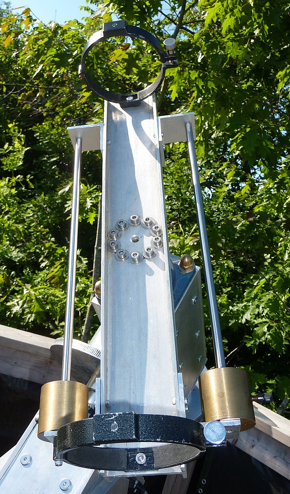
The construction method of building boxes with 10mm thick, aluminium 'planks' is more easily seen. As are all the heads of the multiple furniture screw. These tension all the internal cross studs which hold all the plates together laterally.

The entire mounting can be reduced to a pile of aluminium plates and components simply by unscrewing all the nuts and studs. There is absolutely no reason why anyone could not copy my design given the materials and will to do so. My original design was strictly dictated by the materials becoming available at the nearest scrap yard. Selection of the least cosmetically challenged surfaces avoided the expense of buying more than I needed. Or, worse, buying new.

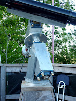
The large, 16mm studs, which run lengthwise inside the corners of the bearing boxes are concealed. Except for their large, brass, domed nuts at each end. These large studs and their nuts compress the massive, self aligning, ball bearing, flange bearings onto the ends of the bearing boxes. This denies the plates the ability to slide lengthways. Meanwhile, the smaller, cross studs press against these larger studs. This is for precise location of the bearing boxes' heavy, alloy plates to further stiffen the construction. I like to think of it as a pre-stressed mounting construction.

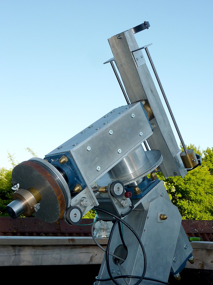
Upmarket mountings usually apply end loads to their bearings. I haven't bothered with that approach but the large, self-aligning, ball bearing races could easily cope with considerable compression. The 50mm stainless steel axes are a close fit in the bearings so any shake [unwanted freedom] is highly unlikely. 

The 11" PA and 8.5" Declination drive wormwheels each have three radial screws with nylon plugs rubbing against the 2" stainless steel main shafts to act as slipping clutches. No movement is required nor desirable to avoid loss of sky location in the drives.The wormwheels had only one screw and plug as supplied. I decided to increase the torque resistance.

AWR's Goto drives are via large stepper motors which I hid in square section alloy tubing for stiffness and physical protection. Early worries about motor overheating were never realised. The motors stay cool even after a full day following the sun in 70F unbroken sunshine. The brass worms are visible and driven by 2:1 toothed belts and pulleys.

The 14' high, plywood clad, pyramidal pier is proving very stable and quickly damps vibration. I was deliberately hitting the pier and mounting support fork with the side of my fist, almost to the point of pain. The Sun's image at 100x merely wobbled slightly and settled quickly again in about one second.

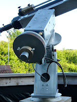
The main PA wormwheel rubs against a 7" diameter cylinder. Which is fixed with multiple stainless steel studs to the Declination axis bearing box.

A Tollok compression/expansion bush is buried tightly inside the cylinder. The Tollok bush clamps itself onto the end of the 50mm [2"] PA shaft. Just as the bush expands strongly against the inside of the cylinder. The cylinder thus acts as a plate bearing to further stiffen the junction of the polar axis with the declination bearing, housing box.

A similar Tollok compression bush is bolted using the 10 fixing/compression screws to the 50cm [30"] long declination saddle. Tollok bushes are often used to carry heavy pulleys and sprockets which drive powerful machines via large electric motors. The exact bush I chose from Tollok's catalogue had the maximum compression sleeve length and largest flange diameter for the 50mm shaft size.

The Tollok bushes are incredibly easy to dismantle. The conical, compression/expansion sleeves are forced apart by removing all 10 normal fixing/clamping screws. Then reinserting several screws into the threaded screw holes provided in the design. Which is incredibly convenient when dismantling the heavy components of the mounting when working alone.

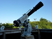
The new OTA balance weights are visible at the top in these images. They help to balance the nose-heavy refractor. A duplicate sliding bar will be added to the other side of the saddle to achieve symmetry of balance. The stainless steel, sliding weight bars are actually hollow with captive nuts in each end. Simple end screw attachment to aluminium angle makes them very user friendly and completely rust free. The large, tubular format ensures a lack of flexure and vibration. They come from the IKEA catalogue at a very modest price indeed.  

For scale, the main counterweight is a turned, weight lifter's 5kg [10lb] disk 9" in diameter. The single counterweight is actually too heavy for the mounted, 6" f/8 refractor. So the tube balance weights are thus helping to balance the entire mounting in a dual purpose mode.

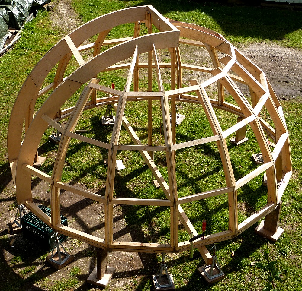
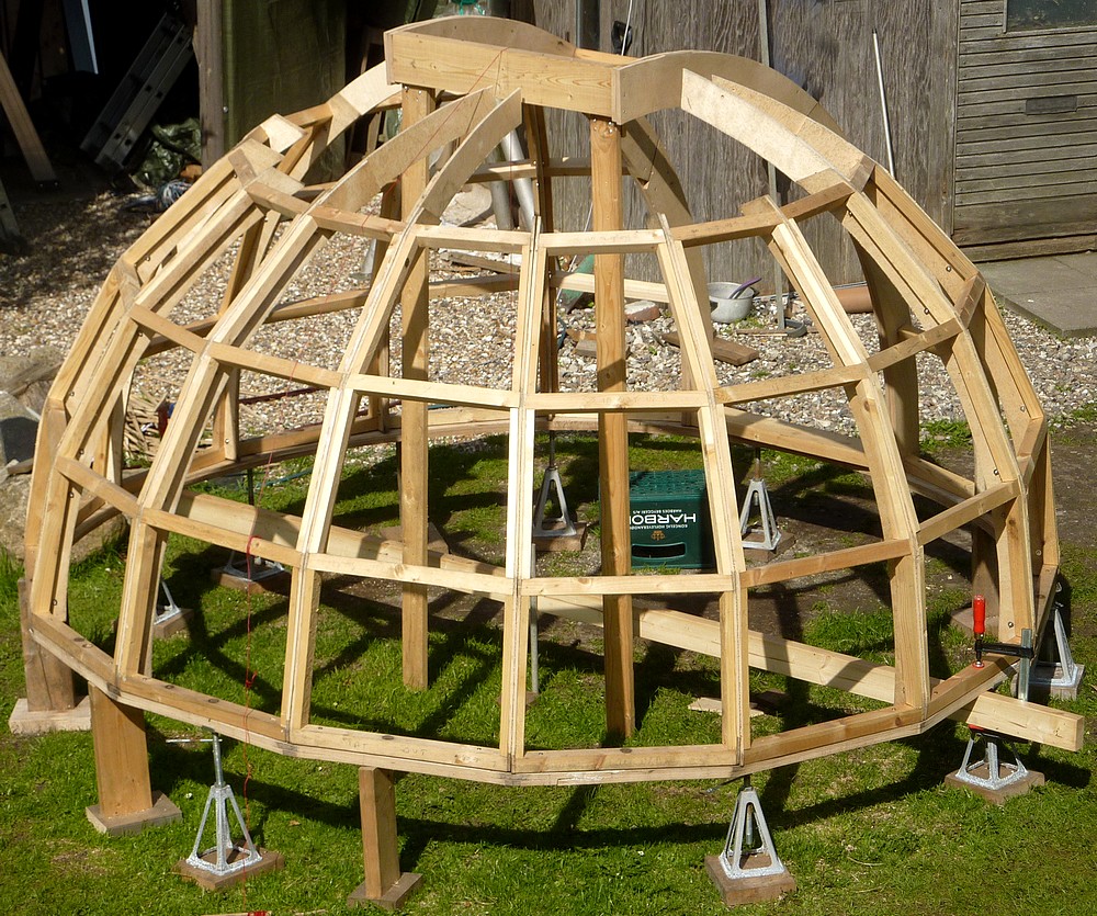
I have struggled with balance weights attached directly to OTAs and can confirm they severely limit mobility. Once an 8' long x 8" diameter OTA has passed 30 lbs it becomes a real struggle to carry it out of storage and up the steep stairs to the observing platform.  Hence the need for a dome to provide permanent shelter and reduce manhandling large OTAs to an absolute minimum.

The stepper motor drive cables pass through the aperture in the reinforced base fork where the polar altitude adjusting, all stainless steel, turnbuckle is located and concealed. A 16mm cross stud provides the pivot for polar altitude adjustment. Which can then be clamped immovably to further reinforce the PA bearing box and the base fork itself. The fork was designed specifically for my 55N latitude. The 10mm thick front plate is made full height for maximum reinforcement of the fork base.

The PA support, fork blades and its base are constructed from solid plates of 20mm aluminium for maximum stiffness and to avoid corrosion. The fork sits on a thick pulley from the scrap yard. Which helps to spread the mounting loads into the thick, laminated, plywood top of the pier. The pulley also provides smooth rotation for polar alignment when the central 16mm stud is loosened down below, inside the pier. This saves me having to struggle with an inaccessible nut hidden inside the fork.

Click on any image for an enlargement.
*

10" f/8 another look + saw sled.

*

The recent failure and dismantling of yet another washing machine provided a second 12" diameter drive pulley. It seemed like a good basis for a new mirror cell which would allow plenty of fresh air around the glass.

The previous, full sheet cell lies in the background and weighs quite a lot. A central hole was for a cooling fan. A full, 3/4" plywood disk had closed the tube. Again with a central hole for the fan.

The two pulleys look made for the job if I add mirror support pads and collimation screws. Their rims are a both a nice 'rattle fit' in my steel, 12" ventilation tube.

Monday: While I ponder the cladding of the dome I am pottering around the octagon looking for earlier oversights. I replaced one larch plank where the original had ugly cutouts for an earlier trapdoor's hinges. The plan now is to hinge the trapdoor beyond the top of the ladder/stairs. Which meant I could close off the obs. floor sides close to the sides of the ladder. More larch sawdust and splinters later and I found I had to add two more floor joists to pick up the added planks nearest the pier legs. My timber is round shouldered. So I was able to slide the joists in on their sides and then bring them upright with a long Bessey F-clamp. Not without some effort I should add! Then the joists just needed a hefty tap with a lump hammer to set them to full depth. Now I just need to screw the flooring down onto them to finish the job.

Tuesday: Another warm and sunny day with hours of H-alpha staring at a rather indistinct sunspot. I am still waiting for the arrival of a low profile T2-T2, helical focuser. Plus a 2.6x GPC to tame the focus shortening of the binoviewer.

I started building a sled for the table saw. This involved making two strips of plywood as runners for the slots and a 2' square x 3/8" sheet of ply for the top. After the runners were made exactly to size I propped them up above the table surface and applied wood glue for the top to rest on. The plywood top was then heavily loaded to ensure close contact. The weights were carefully placed directly over the runners to avoid bowing of the top plate.

Apart from a little glue escaping sideways this went well by the time I had to put the saw away overnight. I need a sled to make repeatable miter cuts on the sides of the trapezium covering panels. Since the angles are all very similar, though right and left handed, there will be a need for small variations in the cut angle.

I shall have to arrange an adjustable push bar and a fence for the sled to make repeatable, angular cuts without waste. The panels are all under 60cm wide but will have to be laid [mostly] to one side of the saw blade for cutting. I'm hoping the 2'x2' sled top will be enough to support the panels without getting in the way.  

Click on any image for an enlargement.
*

16.5.18

Dome building: Rest day, going Solar H-alpha.

 *
Tuesday: I had a rest from dome building and played at Solar H-alpha with my 6" refractor conversion. I was struggling with balancing the 6" even with only one 5kg counterweight. So added the home made, sliding brass balance weights from my home made 7" refractor. I bolted the sliding weight tube, with newly made aluminium brackets, to the side of the 30" long saddle. This helped to balance the relatively lightweight, 6" refractor without having to reduce the mounting's counterweight.

I had crystal clear solar images, with very even surface detail, when I started viewing at 11.30am but the seeing slowly softened throughout the warm and sunny day. It eventually reached 74F or 23C. I am still unable to use my binoviewer even with the 1.6x T-S GPC. It just will not reach focus with a star diagonal fitted. No problem viewing "straight through" except for the near impossibility of tilting my head 50° backwards to use the binoviewer.

I also discovered that the thread on the T-S star diagonal is the same as on the no name diagonal. So the PST filter stack will screw securely in place of the eyepiece holder. The optical path length on the T-S star diagonals is longer than the no name variety.

I can't use the PST eyepiece holder with the undersized T-S GPC when fitted to the binoviewer nose. So I shall have to add two more thumbscrews to get a proper grip. I wonder whether there is enough meat [wall thickness] to cut a groove for a compression band to fit in the PST eyepiece holder? The PST's BF5 [5mm blocking filter] is fitted in the base of its eyepiece holder. So it is probably impossible to add the BF to a star diagonal without making an internal disk to screw into the T-S eyepiece holder. That's the only way to get the compression band fitting I need for the T-S GPC.

Wednesday: Further experimentation proved that I could focus the 26mm Plossls in the binoviewer + 1.6x GPC + T-S 1.25" 90° star diagonal. It required that I push the 2" nose of the Etalon adapter directly into the tailpiece. This doesn't make any sense from a geometric point of view where the PST etalon ideally wants to be 200 mm inside focus. I may have to invest in the other 2.6x T-S GPC which claims zero added path length. Though at the expense of increased magnification.

Thursday: The images show the new, aluminium tailpiece disk I turned in the lathe. I put a step in it so it wouldn't vanish inside. It took ages to make from a roughly cut piece of 10mm plate. A ring is bored to 2" to provide solid support inside the new disk.  Three radial 4mm screws hold the 2" extender.

I could see the whole solar disk but it wasn't as clear as the single 18mm PST Cemax EP. I'm not keen on the Meade 4000 26mm Plossls for binoviewing because of the large eye clearance making it difficult to hold my head still enough at a distance.

Friday: I drilled two more holes in the PST eyepiece holder and tapped them for 4mm thumbscrews. I'm still trying to get the binoviewer focused but don't have enough back focus. Big clumps of Cumulus are making it a tediously slow trial and mostly, error.

Finally, I had focus with the star diagonal, binoviewer and GPC in place. Note how short  is the distance between the etalon and star diagonal. [Arrowed] Just room for a 15mm deep 2">1.25" adapter. The connection between the two components could be achieved by shortening an AOK Swiss PST rear etalon adapter. Instead of which I have ordered a 2.6x GPC and hope that will solve the lack of back focus. T-S claim a 105mm compensation for this GPC. Which should effectively neutralize the focus shortening effect of the binoviewer.

Sunday: I dragged the H-alpha telescope up to the big mounting on the platform. The AWR IH2 handset needed somewhere to rest. Somewhere it would be handy but out of the sunshine. So I hung it from the north side of the sloping plywood pier cladding. Two roofing screws, some washers, some 'pex' tubing for spacing and padding is a bit crude. Very good it was too. As it was within easy reach of the eyepiece of the 6" as I searched for sunspots and prominences. I swear I remember seeing a neat, aluminium hook for the IH2 on the AWR website but can't find it now. The AWR drives have been going all day keeping the Sun in the field of view. Only the power supply warmed up. The motors and electronics remained cool. 

Click on any image for an enlargement.
*

13.5.18

Dome building: Topping out.

*
Time to use the table saw in anger in cutting glue blocks. The wheeled stand is remarkably user-friendly. BTW: Anyone struggling to park the table saw + stand should put their foot on the yellow plate as if it were a normal sack truck. This works a treat. Where, before, I was struggling to nudge the wheeled stand forwards under the miter saw.

The latest view of the dome skeleton after the ribs opposite the slit were adjusted to the correct height and aligned.

I took the pointless [underside] carrying handle off the miter saw stand to allow the table saw to roll cleanly underneath. The miter saw needs to be set with the miter handle well to the left, or right, to allow the table saw to rest against the curved, pivot casting for minimum projection.

Rather than cut two slim, triangular blocks per rib, I cut wider, spacing blocks to fit between the ribs. These were screwed to the slit top board  providing much greater strength. They also avoided splitting the blocks when screwed into place.

I used off-cuts of 2" x 6" x 4" high and cut the bevels to the angles measured with the speed square. The outer ribs required 55° angles which I cut on the vertical on the miter saw. The 2"x 6" block was clamped firmly upright to the back saw fence with a Bessey F-clamp using batten bridges and blocks to avoid accidents. Rather amazingly, the 12" blade could easily manage a 4" deep, vertical cut. Thin packing between the fence and block ensured perpendicularity of the acutely angled cut.

Monday: Still plodding on fitting mitered blocks between the tops of the ribs in "sub-tropical" 70-75F heat. There is quite a serious difference in level of the ribs at the corners of the slit frame. This would cause the covering panels to tip sideways at the top. So I have raised the lower ribs as much as possible to reduce the problem.


Click on any image for an enlargement.
*

7.5.18

Dome building: Onwards and upwards!

*

But not yet. Today, Saturday 5th May, I braced the slit frame to ensure it was central to the dome and level. Then I started extending the foreshortened ribs up to the slit frame. It seemed easiest to resurrect my Inca bandsaw to trim the ends of the arcs by small degrees until they fitted perfectly. It felt hot in the shade-less 63F of a still and sunny May afternoon. Not to complain, though, since it gives me a chance to catch upon weather delayed progress.

By the time I had finished adjusting the slit frame I had only 5" of clearance beyond the zenith. This could easily be increased by changing the 2"x6" top bar for some 3/4" plywood.

Extending the ribs is a very time consuming business. Perfect length, following the same radius as the lower arcs, compound miter angles at the top, overlapping joints [for strength] and straight line alignment with the lower ribs all adds up. Not to mention the blinding sunshine every time I look up to judge the next cut. Then the work is doubled because each rib is doubled.

I have yet to make angled blocks to join the ribs to the slit framework. Even then I have to cut flats on the tops of the extended ribs. Then add vertical struts to give the top tier of trapezium covering panels something flat to rest on. 

With 72F in blinding sunshine it was getting too much for me. So I threw a worn out, white, lightweight tarpaulin over the dome for some shade. The poor man's, "let's pretend we have a white dome," if you like. It makes a far more comfortable workshop with good light. It seemed much larger inside the dome in white. This is typical because white recedes visually on interior surfaces.

Tuesday & 74F hot again under a cloudless sky. Still plodding on fitting rib extensions where the plywood sheets weren't wide enough for a full arc.

Wednesday and already 74+F by 12am. I finished off the last four rib extensions. The two shorter ribs on the open slit sides will have to wait until the geometry is finalized. If I can get the ribs fixed to the observation slit frame I can get rid of the two supporting props.

I can't say I have enjoyed making the rib extensions. With no desire to waste unused arcs there was a lot of fiddly cutting on the miter saw to get it right. Which meant lots of walking back and forth, in and out, and climbing endlessly over the raised dome threshold. Every time I tip my head back I feel dizzy.  There was a lot of head tipping involved. I presume it is my inner ears causing the problem. As I have been going deaf over the last couple of years after terrible bouts of screaming tinnitus. Tomorrow marks a change to cooler weather with thunderstorms.

Time to use the table saw in anger in cutting glue blocks. The wheeled stand is remarkably user-friendly. BTW: Anyone struggling to park the table saw + stand should put their foot on the yellow plate as if it were a normal sack truck. This works a treat. Where, before, I was struggling to nudge the wheeled stand forwards under the miter saw.

The latest view of the dome skeleton after the ribs opposite the slit were adjusted to the correct height and aligned.

I took the pointless [underside] carrying handle off the miter saw stand to allow the table saw to roll cleanly underneath. The miter saw needs to be set with the miter handle well to the left, or right, to allow the table saw to rest against the curved, pivot casting for minimum projection.


Click on any image for an enlargement.
*

4.5.18

Dome building: Dust storm!

*

Friday: I used an angle grinder with 80 grit disk to smooth the rib edges back the vertical struts. A 'proper' industrial dust mask and ear defenders were vital considering the 3/4" of floury fine dust on my forearms by the time I had finished!

The Blackbird's nest at the back of the octagon. A single egg disappeared so it may have been a Magpie nest robbing. The nest was clearly far too exposed to survive completely unscathed.

Aerial views of the dome skeleton before sanding:

Left, taken from the veranda of the octagon. Note the 2x4 crossbar to guide the observation slit installation.

I am amazed I have actually reached this point. My patience is not my finest feature. So I am testing the patience of my blog readers and forum members instead. Though not deliberately. I find having a virtual audience makes up for my lack of determination at times of weakness. One can't easily give up half way through when people are watching. Even if invisibly. Our rural isolation ensures that very few people would ever see my activities in the flesh.

Right, taken from upstairs indoors through a closed window.

I have been very fortunate to have experts in several fields kindly guide my sometimes wavering progress. This dome is certainly not art and it's not high tech nor costly. The basic design has changed considerably from anything I originally envisaged. The materials are readily available. So anyone daft enough to copy my example is certainly welcome to try.

Hemispherical domes are far more popular. Probably more geodesic dome have been built compared with the much rarer trapezium form. My dome has the singular advantage of not needing 3D covering. All the plywood cladding panels will be flat.  I'm hoping the play of light on the facets will diminish its "blot on the horizon."

It could be more easily made by partially cutting out wedges and then bending aluminium or steel square tube. I have no welding facilities so went with timber. For the latter I strongly recommend a sliding, compound miter saw and a compact table saw. Though it could be done with a simpler, portable circular saw. 

Quite honestly, the compound miter saw made this project possible within my skill levels. Or, rather, lack of them. Repeatability and speed of cutting makes ownership well worthwhile. The saw could easily be sold on afterwards if funds are really tight. These saws are very popular on building sites. So a good model should fetch a decent price secondhand. Particularly if the maker is well recognized. 

The DeWalt 12" is a nice piece of kit but has some foolish weaknesses. It is also rather heavy so needs a younger and fitter owner than myself if it is to be considered remotely portable. Though a wheeled stand, like a built-in sack truck, is available from DeWalt. I bought one for my DeWalt compact table saw to save a lot of dead lifting from the shed floor. I like this stand quite a lot and will make good use of it when the covering panels have to be cut out. Which should be quite soon now.
Click on any image for an enlargement.
*


3.5.18

Dome building: Finalising the slit framework.

*

Thursday 3rd May: I have been working on the dome all morning. First I added more screws to bring the tally up to 6 per pair of joined ribs. This was followed by pilot drilling and screwing the base ring to the bottom ring of horizontal struts with 6x80mm Torx screws.

Then I added a 2x4 to the underside of the base ring to bisect the dome and provide an accurate  reference for dome level and height. It also provides a check for squareness of the observation slit frame relative to the dome gores.

I carefully marked the middle of the 2x4 beam using both a tape measure and checking with a laser rangefinder. I also checked the distance from the center of the top beam down to the inside of the gores at the base ring. The two measurements were within 5mm of each other after several trials.  The height of the dome was then confirmed at 1.5m [5'] inside.

I then turned my efforts to the slit frame. First I cut away its props to allow the top of the frame to sink relative to the dome. Then the opposing ribs had to be cut back as they were overlapping the slit frame, top bar by about 6". 

The plumbline showed I had now increased the sky clearance beyond the zenith to 6". This is not remotely critical IMO. How often does one want to stare at the exact zenith through a telescope? Only half the aperture matters anyway for a full aperture view. The other half is already seeing the sky though the open slit.

The side ribs ought to align with the underside of the slit arcs and now they do from both sides. The [slit opposing] gore ribs were chopped off after dropping verticals from the slit frame's top beam. [See image above.]

Next I have to add short plywood arcs to complete the ribs so that they join the slit frame as a continuation of the dome's external hemisphere.

All the ribs need sanding to even out the lumpiness from roughly jigsawing the flats for the covering panels. I keep wondering if glue is necessary if I can climb on the structure without so much as a creak [from the woodwork.]

Suitably clad in an industrial dust mask, hearing defenders, goggles and a hat I sanded the ribs smooth on their edges. I used an angle grinder and 80 grit disk. By the time I had finished, the dust on my forearms was 3/4" of an inch thick! The racket was drowned out by a neighbour cutting up pallets for firewood and another resurfacing his drive with a JCB. 

Click on any image for an enlargement
*

1.5.18

Terrestrial 90mm binoviewing telescope.

*
With the foul weather preventing outside work I'm having another look at the binoviewing telescope. I received a 1m length of 100mm aluminium tube which proved to be 100mm OD. Not very helpful when I had foolishly expected 100mm bore! Beggars can't be choosers and one must use what one can get. I found no other sensible Danish outlet for aluminium tube. Most are wholesale dealers only and sell in only 6m [nearly 20'] lengths!

The bare glass of the 90mm f/11 Vixen objective lens is actually 93mm in diameter. This doesn't leave much room inside my 96mm bore tubing. Any tube would have to be under 1mm wall thickness. There followed a search for potential "cell" material. None of my aluminium tubing was of the slightest use. Then I spotted a bleach bottle. Which turned out to be only slightly undersized. Further searching produced some flashing but nothing I tried would make a strip perfectly round. I tried rolling it around numerous diameters but it always made ridges.

Finally I spotted an old aluminium case from a mains clock now long forgotten. It proved to be only slightly tapered once I had very carefully cut the battered base off. It was now a perfect sliding fit in the 100mm tube and quite snug on the objective lens itself.

A lens does not want to be compressed or it will spoil the optical accuracy and thereby the image. If the aluminium shrinks in a frost it could actually damage the lens! It might be worth slitting the cell tube to avoid the risk of thermal damage.

So I set about sanding the old paint away to give just a little more headroom. Then I drilled pairs of holes at 1/6th intervals around the circumference and sawed a line between them. The idea is to allow the glass to survive a hard frost as the cell contracts. The cell tube obviously cannot become larger than the inside diameter of the main tube but the sleeve is only a snug, but not tight, fit. It's ugly, but beggars can't be choosers. I had nothing else which would fit in the main tube that was also thin enough for the lens to fit inside.

With the biconvex crown element resting on a foam cup I carefully lowered the tubular "cell" around the glass. Still snug but just manageable. Rings cut from the bleach bottle will make useful lens stops so the glass will not fall out. It would have to slide out because it can't possibly tip in such tight surroundings.

Careful measurement of the near focal point requires a 84cm length to the base of the Baader 45° erecting diagonal from the back of the objective glass. This is with the binoviewer in place in the diagonal and carrying a pair of Japanese 26mm Meade 4000 Plossls for about 42-45x. The actual power will depend on the effective glass path length of the diagonal. Assuming 100mm to be added to the original focal length plus a similar GP of 100mm for the binoviewer. Say 1200/26 = ~45-46x.

Some allowance for infinity focusing will be further inwards. I had no chance to check this distance in the rain but will as soon as the weather allows. I need this figure for infinity to ensure I have enough focus range. A suitable focuser has yet to suggest itself. A helical focuser would be nice for terrestrial use and avoid the usual focusing knobs/wheels sticking out.

Later I used the garden gate to check the likely nearest focus at about 20 yards. Anything nearer and one might as well just use ordinary binoculars. My earlier measurement of focus was strangely awry. I added a batten to rest on and internally blackened tubes to help reduce glare. The focus was now 78-84 cm from the back of the object glass to the front face of the Baader 45° diagonal's body. A range well beyond any helical focuser I have found so far. I had better start looking for a secondhand focuser with a range of at least 60mm. No obvious candidates within the Newtonian and SCT ranges. Which means a refractor focuser is required. It looks as if the original Vixen focuser will have to do.


*